Welcome to akYtec!
 
Call us now: +49 (0) 511 / 16 59 672-0

ITP11 Process indicator 4-20 mA (loop-powered)

SKU: ITP11
The ITP11 Process Indicator 4-20 mA is a universal process display for monitoring industrial processes. This digital process meter is ideally suited for quick and convenient developing of visualization systems for various applications, e.g., water supply or thermal processing. The digital display ITP11 can serve both as a useful additional display of the measured values on site and as a part of a sophisticated visualization. This industrial display is loop-powered and causes a voltage drop to the current loop of 4V maximum.

LED color4-20 mA inputloop-poweredeasy mounting in a Ø22.5 mm holequick mountingcompact designthe process display can be installed into a push-button boxaccuracy 0.2%Character height 14 mmAmbient temperature

* Required Fields

- +
Product Description
    Details

    4-20 mA digital display for universal application

    The ITP11 Process Indicator 4-20 mA is a universal process display for monitoring industrial processes. This digital process meter is ideally suited for quick and convenient developing of visualization systems for various applications, e.g., water supply or thermal processing. This digital display can serve both as a useful additional display of the measured values on site and as a part of a sophisticated visualization.

    Compact design and high IP rating

    Thanks to standardized cylindrical form and minimal dimensions, this 4-20 mA process display fits into a standard 22.5 mm mounting hole for indicator lights or push buttons. The digital displays can be installed in a space-saving, quick and convenient way allowing the integration of a large number of these current loop indicators in control cabinets or panels.

    The 4-20 mA digital display ITP11 ensures excellent legibility in various lighting conditions, from wide angles, and considerable distances even at low current.

    4-20 mA signal in digital display

    The 4-20 mA process display ITP11 is designed to accept any sensor or transmitter with a 4-20 mA output. The current loop indicator ITP11 does not require any auxiliary power supply; the device is supplied directly from the 4-20 mA current loop.

    Functions and features:

    • - Signal scaling
    • - Adjustable decimal point position
    • - Display range of -999…+9999
    • - Square root function (for special transmitters)
    • - Digital filter
    • - Alarm function (blinking when exceeding the setpoints)
    • - Error indication when exceeding the measuring limits
    • - Access protection
    Supply current From current loop
    Inputs 1
    Input signal 4-20 mA (2-wire)
    Measuring range 3.8...22.5 mA
    Normal operation 3.2...25 mA
    Voltage drop, max. 4 V
    Accuracy 0.2% + 1 digit
    Display LED, 7-segment display
    Character height 14 mm
    Display colour red or green
    Number of digits 4
    Sampling time 1 s
    Dimensions 48 x 26 x 65 mm
    Weight approx. 30 g
    Protection class III
    Ambient temperature -40...+80 °C
    Storage temperature -25...+80 °C
    Humidity up to 80% (non-condensing)
    FEEDBACK
Additional Information
FAQ

    FAQ

    What is the lifetime and the MTBF of ITP11 process indicators?
    The lifetime is 8 years, and the MTBF is 80,000 hours.
    Rate the answer?
    Can you tell me how the micro calculates what digit to display? Does it round up to the next digit, or does it truncate?
    If the decimal point position has been set to 0, and the current calculated value is, say, 1.7, the display will read 1, i.e. the value will be truncated.
    Rate the answer?
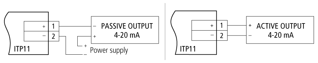
    What type of signal does the ITP11 support? How should I connect it?
    The ITP11 supports any 4-20 mA signal from any piece of equipment with an output of this kind. The connection should be performed in series.
    Rate the answer?
    Can I directly connect the ITP11 to an analog 4-20 mA output?

    That depends on the output, whether it is a passive or an active one. For example, the analog outputs of our Programmable Relay PR200 are passive outputs, meaning that any of them requires an external voltage source. In case of an active analog output, no external voltage source is required.

    4-20 mA Anschluss
    Rate the answer?
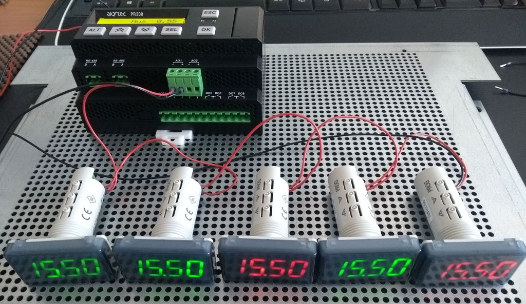
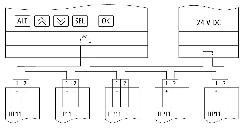
    Can I connect several ITP11 displays to the common analog output? How should I connect them, in series or in parallel?

    The number of the connected displays depends on the available supply voltage because each ITP11 causes a voltage drop of about 4 V. For example, an external voltage source of 24 V connected to a 4-20mA analog output of a Programmable Relay PR200 supports up to 5 ITP11 displays (without any other loads).

    The connection should be performed in a series circuit.

    Rate the answer?
    I have connected the ITP11 but it doesn’t switch on, what should I check?

    First of all, check the polarity of the signal.

    Also, make sure that the 4-20 mA signal is available. If the signal is too low (< 3.8 mA), there is not enough power to switch on the process display.

    Check the wiring. A wire may be loose or not connected to the terminals.

    Check the transmitter output. If the output is passive, you need an auxiliary voltage supply.

    Rate the answer?
    Can I connect a 0-20 mA signal to an ITP11? What about a 0-10 V or a PT100 signal?

    No, you cannot do it. The ITP11 supports only 4-20 mA.

    For a 0-10 V signal, you can use our Universal Process Indicator ITP14.

    For a Pt100 signal and many other signals for temperature measurement, we offer the Temperature Display ITP16.

    Please feel free to contact us if you need support.

    Rate the answer?
    Which voltage supply does the ITP11 require: 24 VDC or 230 VAC?
    The ITP11 doesn’t require auxiliary power and is supplied directly from the current loop.
    Rate the answer?
    What software do I need to program the ITP11?

    You don’t need any software to program the ITP11. The programming is carried out by using three buttons on the ITP11’s cylindrical body.

    Please, watch our video tutorial ‘ITP11 Process display 4-20 mA. First Start’ to get more information.

    Rate the answer?
    Should I program the display before or after the installation?
    Technically, it doesn't matter; but in terms of convenience, it depends on your particular case.
    Rate the answer?
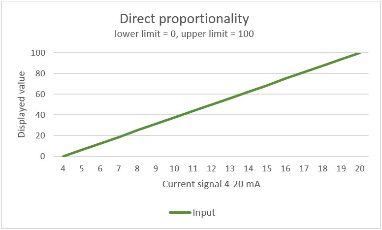
    How can I scale the measuring limits of the ITP11?

    To scale the measuring limits, please proceed as follows:

    - Connect the device to a 4-20 mA signal to provide power.

    - Hold down the PROG button for at least 3 seconds to access the parameter menu.

    - When the display shows ‘0’, enter the password “5” using the UP and DOWN buttons. The same buttons are used for navigating the menu.

    - Once you access the menu, the word “PS” will appear. Navigate the menu to find the parameter ‘di.Lo’ and press the button PROG to access it.

    - Set the required value and press PROG to save it and exit.

    - Proceed the same procedure for the parameter ‘di.Hi’.

    To exit the parameter menu, hold down the button PROG for at least 5 seconds.

    Please, watch our video tutorial ‘ITP11 Process display 4-20 mA. First Start’ to get more information on programming the device.

    Rate the answer?
    If I need to show a percentage value, what should the measuring limits be?

    The lower measuring limit (the parameter di.Lo) should be set to 0.

    The upper measuring limit (the parameter di.Hi) should be set to 100.

    Rate the answer?
    How can I set the alarm limits of the ITP11?

    To set the alarm limits please proceed as follows:

    - Connect the device to a 4-20 mA signal to power it

    - Hold down the PROG button for at least 3 seconds to access the parameter menu

    - When the display shows ‘0’, enter the password '5' using the UP and DOWN buttons. The same buttons are used for navigating the menu.

    - Once you access the menu, the word ‘PS’ will appear. Navigate the menu to find the parameter ‘d.FnC’ and press PROG to access it.

    - Select the required alarm logic (see the figure below) and press PROG to save it and exit

    Process display 4-20 mA Alarm configuration

    - Navigate the menu to find the parameter ‘SP.Lo’ and press PROG to access it

    - Set the required lower setpoint limit and press PROG to save it and exit

    - Do the similar procedure for the parameter ‘SP.Hi’ (upper setpoint limit)

    To exit the parameter menu hold down PROG for at least 5 s.

    Please, watch our video tutorial ‘ITP11 Process display 4-20 mA. First Start’ to get more information on programming the device.

    Rate the answer?
    Can I switch on/off its the output of the ITP11 as a function of the signal value at its input?

    No, you cannot do this. The Process Display ITP11 isn’t equipped with an output, and its alarm function isn’t implemented by means of an output. This function just makes the display blink when the process value is outside or within the previously-set limits.

    If there is required an output signal to trigger a relay, you can use our Universal Process Indicator ITP14.

    Please feel free to contact us if you need support.

    Rate the answer?
    How to change the access protection password?
    The password cannot be changed. However, it can be disabled. Just enter the parameter menu and set the parameter ‘PS’ to ‘OFF’.
    Rate the answer?
    What is the IP rating of this display?

    Proper device installation (see User Guide) warrants protection against dust and water (IP65 on the front). Because of the exposed terminal block, the rear part of the enclosure is rated much lower – IP20.

    Process display 4-20 mA IP rating
    Rate the answer?
    What is the ITP11’s input resistance?
    Since the current flowing through the ITP11’s input tends to vary from 4 to 20 mA, the input resistance changes inversely proportionally to it. For the sake of convenience, we declare the maximum voltage drop (4 V) instead. Of course, you can use this voltage to calculate the input resistance depending on the current if needed.
    Rate the answer?
    In what colors is the display available?

    The enclosure is only available in grey color. The LEDs can be ordered in red or in green color.

    Rate the answer?
    What conductor cross section is permitted?

    The maximum cross section of a solid conductor is 1.5 mm2.

    The maximum cross-section of a stranded conductor is 0.2 – 0.75 mm2.

    Rate the answer?
    What is the ITP11’s accuracy? What about the sample time?

    The accuracy is 0.2 % + 1 digit.

    The sample time is 1 second.

    Rate the answer?
    Is the ITP11 protected against overload currents?
    There is no overload protection at the ITP11 input, so please ensure that the input current is lower than 25 mA.
    Rate the answer?
    What is the maximum permissible distance between the ITP11 and the signal source?
    The maximum recommended distance is 100m. However, we recommend keeping it as short as possible because the resistance of a long conductor can affect the signal value.
    Rate the answer?
    What diameter should the mounting cutout be to install this display?
    The device is designed for panel mounting in a borehole of Ø22.5 mm (see User Guide, Appendix A).
    Rate the answer?
    Do you have an ePLAN 3D model of this display?

    The ePLAN 3D model is available under the tab ‘DOCUMENTS AND SOFTWARE’ on the product page. There is also a STEP model available under the same tab.

    Rate the answer?
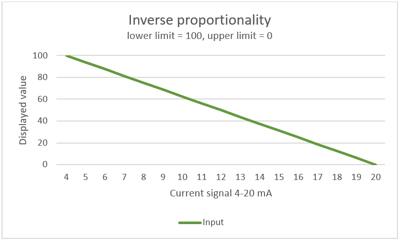
    Is it possible to apply the lower measuring limit to the highest process value and the upper limit to the lowest process value?

    The ITP11 Process Indicator can be set for either direct or inverse proportionality:

    proportionality ITP11 process display proportionality ITP11 process display
    Rate the answer?