1. Pre requirements
For this you will need a few items:
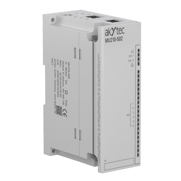
- akYtec Mx210 I/O module
- akYtec Tool PRO
- micro-USB cable
- Ethernet cable
- Router/ethernet switch with connection to the internet
- 24V DC power supply
- PC
2. Setting up Mx210 in akYtec Tool PRO
2.1. Pre requirements
For this you will need a few items:
- akYtec Mx210 I/O module
- akYtec Tool PRO
- micro-USB cable
- PC
2.2. Connecting Mx210 WITH Tool PRO
Connect your PC to Mx210 module via micro-USB cable (location of micro-USB is shown on picture 2.2.1) and open Tool PRO.

Picture 2.2.1 Location of micro-USB labeled with 6
Now Mx210 needs to be configured in Tool PRO Next, Mx210 needs to be configured in Tool PRO; to do so, click on Add_devices button (1.), then chose COM as interface (2. , in this example it is COM4, but in general it could be different number), then use akYtec_Auto_Detection_Protocol as Protocol (3.), then click on Find button (4.), now Tool PRO will establish communication with Mx210. After communication has been established, select Mx210 (5.) and click on Add_devices button (6.). Previous steps are shown on picture 2.2.2

Picture 2.2.2 Adding Mx210 in Tool PRO
2.3. Updating Mx210 firmware
For Mx210s purchased before year 2025, it is important to update device’s firmware to ensure compatibility with akYtec Cloud.
Newest firmware files, for all Mx210s, can be found on any Mx210’s webpage in “Documents and software” section, as shown on picture 2.3.1.

Picture 2.3.1 Newest firmware for Mx210
Once the file has been downloaded it can be opened, go to the file and unpack it. Once files have been unpacked go to Tool PRO and click on Firmware_update_local (1.), then select From_file (2.) and click Continue button (3.) as shown on picture 2.3.2.

Picture 2.3.2. Updating Mx210’s firmware
After that new window will appear, go to folder with files and select file with exact name of your device (full model name) and click Open button, then new window will appear, on that window select the device (if you have multiple Mx210 devices connected to PC) and click on Continue button as on picture 2.3.3.

Picture 2.3.3
During the update, new window will appear showing progress as on picture 2.3.4.

Picture 2.3.4
When the update is complete, a new message will appear, as on picture 2.3.5.

Picture 2.3.5
2.4. Configuring Mx210 in Tool PRO
Now that Mx210 has been added in Tool PRO, it is important to set it up properly for connection to Cloud. Parameters that have to be changed are:
- In Network\Ethernet change DHCP to ON
- In Network\Cloud set Cloud_connection to ON
- In Modbus_Slave\Access_from_Cloud enable and give access for parameters depending on your needs**
- Set the Password for Mx210
- Click on Write_parameters
- Turn OFF Mx210 (remove the micro-USB cable and the 24V DC if you have applied it)
All previous steps are shown on picture 2.4.
**Note:
If only reading of I/O values is needed Configuration and Output_control parameters can be Disabled.
If you are unsure of your project requirements, enable everything.

Picture 2.4 Configuring Mx210 in Tool PRO
3. Connecting Mx210 to akYtec Cloud
3.1. Pre requirements
For this step you will need:
- akYtec Mx210 I/O module
- Ethernet cable
- Router/ethernet switch with connection to the internet
- 24V DC power supply
- PC with connection to akYtec cloud
On your PC, in your web browser go to akYtec Cloud; if you do not have an account, click on Sing up (1.)
If you have an akYtec Cloud account, type in your credentials and Log in.

Picture 3.2.1
Once you have logged in click on the Administration button as shown on picture 3.2.2.

Picture 3.2.2
Then click on Devices (1.), if you do not see it, click on 3. To expand the menu and then click on Add button (2.) as shown on picture 3.2.3.

Picture 3.2.3
Now choose your device type (1.), but select Autodetection option, then type in ID (2.)(ID is serial number of your devices, which can be found on side of your device or go back to Tool PRO and click on Device_information and copy S/N as shown on picture 3.2.5), give your device a Name (3.) (this can be any name you choose) and click on Create button (4.). Previous steps are shown on picture 3.2.4.

Picture 3.2.4

Picture 3.2.5 Reading serial number of Mx210 from Tool PRO
Now type Password in (1.) and click the Save button (2.), as shown on picture 3.2.6. After changes have been saved, click on View_device button (4.).

Picture 3.2.6
If everything was done correctly, whole list of Mx210’s parameters will be displayed, as on picture 3.2.7.

Picture 3.2.7 Parameter list after successful connection
And that is it!
3.3. Connecting to Cloud (Manually)
On your PC, in your web browser go to akYtec Cloud, if this is you do not have account click on Sing up (1.)
If you have an akYtec Cloud account, type in your credentials and Log in.
Picture 3.3.1
Once you have logged in click on the Administration button as shown on picture 3.3.2.
Picture 3.3.2
Then click on Devices (1.), if you do not see it, click on 3. To expand the menu and then click on Add button (2.) as shown on picture 3.3.3.
Picture 3.3.3
Now choose your device type (1.), then type in ID (2.)(ID is serial number of your devices, which can be found on side of your device or go back to Tool PRO and click on Device_information and copy S/N as shown on picture 3.3.5), give your device a Name (3.) (this can be any name you choose) and click on Create button (4.). Previous steps are shown on picture 3.3.4.
Picture 3.3.4
Picture 3.3.5 Reading serial number of Mx210 from Tool PRO
Now type Password in (1.) and click the Save button (2.), as shown on picture 3.3.6.

Picture 3.3.6
All that is left to be done is to add the I/O that you want to see or control using Cloud. To do se, click on Parameter_settings (1.) and click on + sign (2.) as shown on picture 3.3.7.

Picture 3.3.7 Adding I/O of Mx210 to Cloud
For example, we are going to show how to add real type parameter which in this situation will be only read from Mx210.
Give your parameter a Name (1.), Code (2.) should be same as Name, Register address (3.)( if you do not know address of a register go back to Tool PRO and click on Parameters_List to see table with all registers, as shown on picture 3.3.9), Data Fromat (4.) (Can be found from Tool PRO, as shown on picture 3.3.9), Unit of measurement (5.), Precision (6.)(Since we are monitoring REAL/FLOAT type data, we can choose how many decimal point there will be), because we are transmitting REAL type data, here we have to choose (7.) an at the end click on Save button (8.). Previous steps are shown on picture 3.3.8.

Picture 3.3.8

Picture 3.3.9 Parameter list in Tool PRO
NOTE:
On picture 3.3.8 you can see Read and Record (write) function fields, every parameter has different function for itself and this is specified in Parameter List (picture 3.3.9), but even if you can write to the device that value of that parameter, it is not necessary to use that function (for example Write function 16) if you only want to monitor its value.
Units (5.) on picture 3.3.8 can be chosen according to your needs, here we selected none.
After all the previous steps, results should look like pictures 3.3.10 and 3.3.11.

Picture 3.3.10 After succesful opperation of adding Mx210 to akYtec Cloud Mx210 will indicate that it was updated

Picture 3.3.11 After succesful configuration of transmited paramiter, recorded values will be shown in device’s table (3.) (Date/Time of recording parameter and it Value (here it is 50.18 on the right side)) or on Graphs