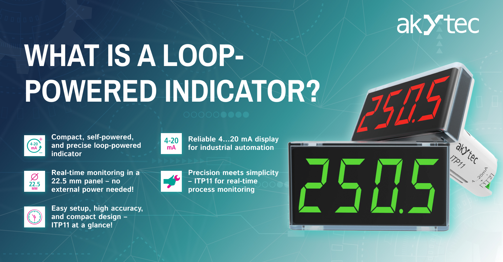
The ITP11 is one of the most reliable and efficient loop-powered indicators in akYtec’s product range. But what makes it so successful over the years? Let’s explore its working principle and applications in more detail.
Principle of Operation
A loop-powered indicator is a measuring device that operates using the current signal in the range of 4…20 mA. It displays real-time data received from sensors measuring pressure, temperature, regulators, switches, actuators, and valves.
The ITP11 indicators come in two design formats:
- ITP11 – Mounted directly into a 22mm button hole on the control panel.

- ITP11-W – Can be mounted either on a control panel or on a pipe.

Users can configure various signal processing and display parameters, including minimum/maximum values, scaling, time delays, and signal damping.
Purpose of Loop-Powered Indicators
Loop-powered indicators serve as measurement devices that process analog signals from sensors or other equipment with a 4…20 mA output. Their primary function is to display measured physical parameters on a digital screen or integrate them into a data communication system. In some cases, they can also generate control signals for external devices.
Industrial Applications
These indicators are widely used in industrial automation and process control systems as local measurement units for primary sensors with a 4…20 mA output. They are commonly applied in:
- Temperature and humidity control systems in industrial facilities.
- Automation in oil refining and distribution plants.
- Production lines for construction materials.
- Pumping stations for various purposes.
- Water treatment, purification, and wastewater management in municipal and industrial sectors.
- Boiler automation systems.
- Industrial complexes for building material production.
Working Principle
A loop-powered indicator connects in series with the 4…20 mA signal circuit between a sensor and an analog input device (e.g., ITP11). It converts the current signal into a digital display output based on user-defined settings. Programming is done via buttons on the side of the indicator (for ITP11) or on the front panel (for ITP11-C). Users can set measurement range limits, scaling, units of measurement, damping, and alarm thresholds. The built-in diagnostic system monitors the indicator’s performance.
Advantages of Loop-Powered Indicators
- Easy installation – Compact and can be mounted close to sensors.
- Simple configuration – Parameters are set using an intuitive menu.
- Direct process monitoring – Provides real-time data access.
- Microprocessor-based control – Ensures high accuracy.
- Visualization capability – Suitable for process monitoring applications.
Limitations
- No communication interface – Cannot transmit data to external devices.
- Limited measurement type – Only measures current values.
Despite these limitations, loop-powered indicators like the ITP11 remain an essential tool for industries requiring accurate and reliable local measurement solutions.

