Our new Modbus TCP I/O modules of the MX210 series offer a great selection of useful functions, making them the perfect choice for complex and large-scale, as well as minor projects. In this blog post we will show you how you can use the Raspberry Pi 4 Model B as a Modbus Master with our MX210 modules to display measured temperature values on the ITP11-W. Also, we have created a video covering the same topic which you can see below.
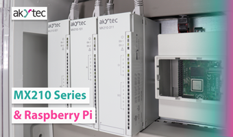
The example setup comprises (1) the analog Modbus TCP input module MV210-101, (2) the analog Modbus TCP output module MU210-501, (3) the Raspberry Pi 4 Model B and (4) the digital process display ITP11-W.

The Modbus TCP I/O modules connect to the Raspberry Pi via a bypass-enabled daisy-chain topology. A Pt100 temperature sensor is attached to the input module MV210-101 to achieve a 3-wire measurement. The digital process display ITP11-W is loop powered via the output signal, 4 - 20 mA, of the analog MU210-501.
With our free software tool akYtec Tool Pro, all MX210 modules can be configured easily.

The CODESYS Development System V3 and the runtime system CODESYS Control for Raspberry Pi are used to program the Raspberry Pi. The runtime system must be integrated as a package in CODESYS and additionally installed on the Raspberry Pi.


CODESYS Development System V3:
>>>https://store.codesys.com/de/codesys.html
CODESYS Control for Raspberry Pi:
>>>https://store.codesys.com/de/codesys-control-for-raspberry-pi-sl.html
The next step is to create a new CODESYS project and to name it. We select the runtime featuring multi-core capabilities, making possible industrial use, and structured text (ST) as the programming language. In the device tree, we click Device to open the communication settings. (1) First, we input the correct IP address of our PC. Please make sure that your PC is in the same ethernet network as the Raspberry Pi and the Modbus TCP I/O modules. (2) The second gateway is the Raspberry Pi. Please provide the correct IP address in the respective text field. Afterwards, the username and password for the Raspberry Pi have to be entered.

After establishing a reliable connection to the Raspberry Pi, we add a new ethernet interface to the device tree. Here, the IP address of the PC, as well as the default gateway, have to be provided. Then we add a Modbus TCP Master, the Raspberry Pi, and two Modbus Slaves, the MX210 modules, to the Modbus network. Be sure to always insert the correct IP address of the respective device.

The next step is to write a small program for assigning the measured temperature value to the analog output. We add a Modbus channel to the MU210-501 to write the output variable to the Modbus register of the first analog output. The parameter list in akYtec Tool Pro includes all register addresses with additional information of the respective device in a table. We attach the output variable from our program to the newly created Modbus channel. Now we are going to create a second Modbus channel to read the value from the first analog input of the module MV210-101. The correct register address can also be taken from the parameter list in akYtec Tool Pro. Finally, we connect the Modbus read channel with the variable that holds the measured temperature.

Now let us start the CODESYS runtime for the Raspberry Pi. For that, we click Tools > Update Raspberry Pi. A window will open for the configuration of the Raspberry Pi.

Here you can see the currently installed version of the runtime package on the Raspberry Pi is 4.1. We enter the username and password and start the runtime afterward. The program is now ready to be uploaded. Please click Online > Login and confirm overwriting the existing program. The perspective in the Development System will change to the online debugging mode that allows for a clear overview of all relevant program variables including the measured temperature.

After a successful configuration, the measured temperature value from the MV210-101 is passed to the analog output module MU210-501 so that the sensor signal can be displayed on the ITP11 correctly.
