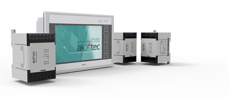
When developing an automation system using CODESYS, one often faces the task of implementing a fieldbus system. For example, there is a need to carry out climate control in a vegetable storage facility based on the akYtec SPK207 control panel. Since the SPK207 does not have its own inputs and outputs, expansion modules must be used. There is the possibility to connect the akYtec Mx100 I/O modules via the RS485 interface as well as any other modules via the ethernet interface to this control panel. This article details the steps required to properly configure the SPK207 for data exchange via Modbus protocol in CODESYS v3.5 SP3 Patch 5.
General technique for configuring interfaces in CODESYS 3.5
Interfaces
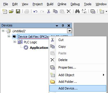
When the SPK207 is successfully connected to the PC (see Appendix C in the User guide or watch the video tutorial), you can open any previous project in CODESYS or create a new one. The Alt+0 keyboard shortcut opens the Device tree, so that you could right-click on the target device (akYtec SPK2xx) and select the Add device option in the context menu.
Among the appearing interfaces you have to left-click Modbus to select item Modbus COM of the same target device version or an older one.
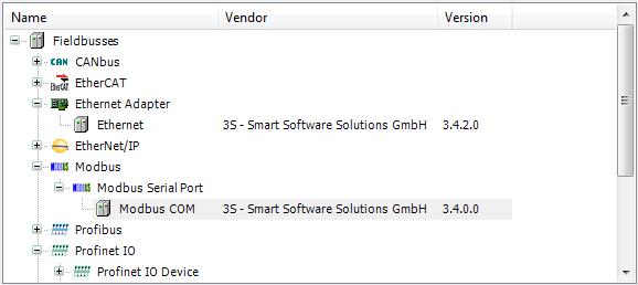
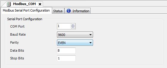
Confirm your selection by clicking the Add device button in the dialogue window. Now a serial port is available in the Device tree. You have to double-click port Modbus COM to open tab Modbus Serial Port Configuration and set the required parameters.
In a similar way you can add the Ethernet port. Just select Ethernet in the Add Device dialogue instead of Modbus.
SPK207 as Modbus Master
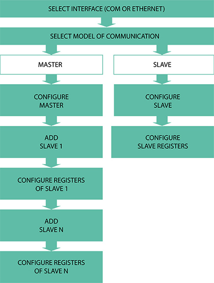
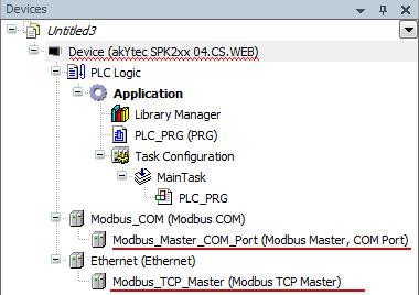
If the desired interface of the SPK207 is to be used as Master, a Master device should be added in the Device tree to this interface. First, add a master device to the "Modbus COM" port by using the option Add Device again. In the opened window select Modbus Serial Master for the COM port or Modbus TCP Master for the ethernet port.


Now the Master devices are available in the Device tree. To configure these devices, correspondent editor can be opened by double clicking on the entry of the master in the device tree.
The Modbus TCP Master has two configuration parameters: Response Timeout and Socket Timeout.

The Response Timeout parameter defines the time interval in which the master awaits the response from the slave. If there is no response during this interval, the master then polls the next slave device. This timeout is taken over for each slave device.
The Socket Timeout parameter defines the maximum period of time in which the master waits for the coming TCP/IP packages.
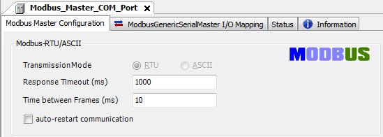
The COM interface has a similar configuration procedure, but you have to set the Time between frames parameter sinstead of the Socket interface parameter. This parameter defines the length of time that the master waits between the last response (or timeout) and the next query.
When the Master devices are configured, it is time to add Slaves through the already well-known Add device dialogue window. Just select Modbus Slave or Modbus TCP Slave, depending on the port type (COM or Ethernet).


Now the Slaves are available in the Device tree, and you can double click to open the configuration dialog.
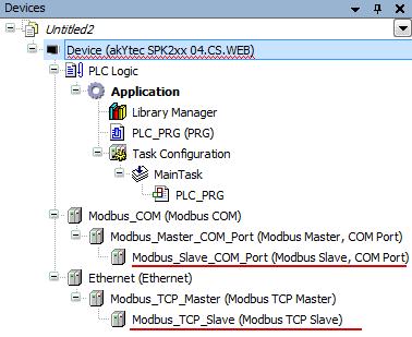
The Modbus TCP Slave entry has the following parameters:
- Slave IP Address – the IP-address of the Slave
- Unit-ID – the network address of the Slave device in the range between 1 and 247
- Response Timeout – the time interval in which the master waits for the response from the slave device. The timeout specified here overwrites the general setting Response Timeout of the associated master.
- Port – the port number of the Slave.

The Slave device connected to the COM port has similar parameters:

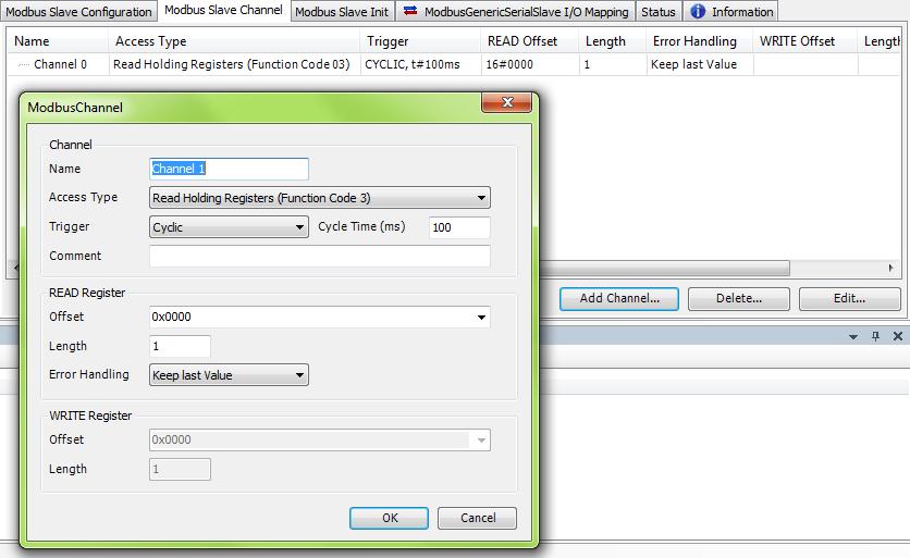
The further settings are about specifying the communication channels. A channel is a group of register addresses which are arranged one after the other and are only queried for a certain function. To add a channel, click on the Add Channel button in the Modbus Slave Channel tab and then set the necessary parameters in the opened window. All parameter descriptions can be found in the Codesys Online Help (Ctrl + Shift + F1).
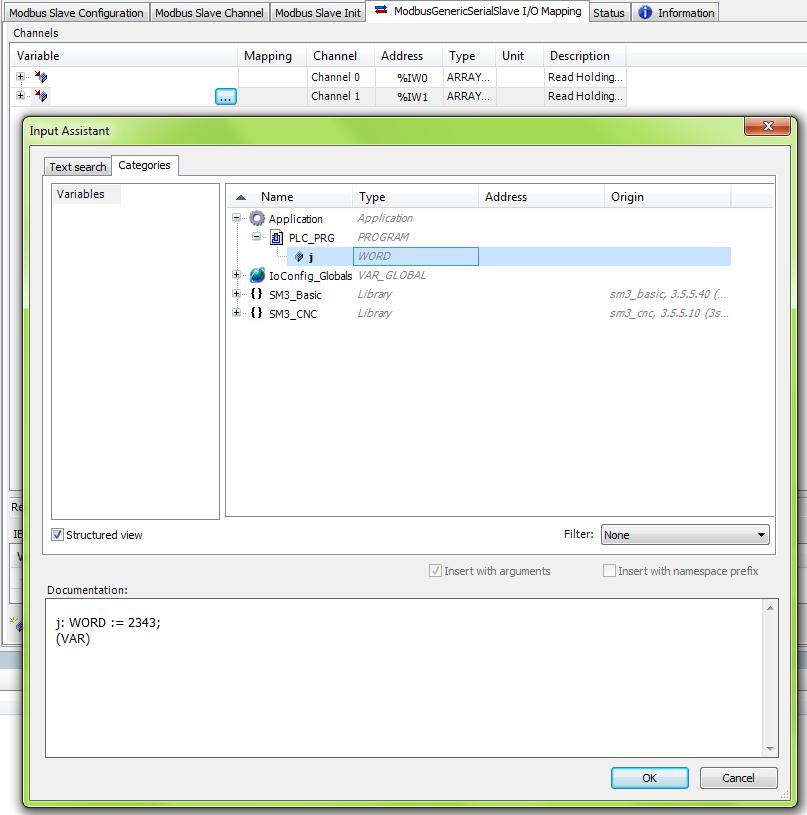
When all desired channels are added, activate the ModbusGenericSerialSlave I/O Mapping tab to assign the variables already present in the project to the input and output channels. Simply double-click the field of the required channel in column Variable and click on the button now available to access  to access Input Assistant. Here you can select any project variable and assign it to any channel after pressing OK.
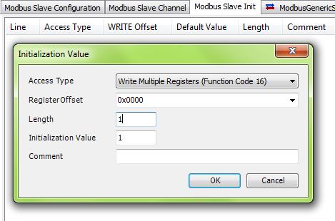
There is also a Modbus Slave Initin the configuration dialog of the slave device. This tab is for previously data initialization. For example, when it is necessary to set a sensor type before starting the data exchange. The procedure is similar to that for channel addition.
SPK207 as Modbus Slave
Whether the Ethernet port or the COM port of the SPK207 is to be used in slave mode, a slave device should be added to the Device tree. Simply select Modbus Serial Device for the COM port or Modbus TCP Slave Device for the Ethernet port in the dialogue window Add Device.


Now the slave devices are available in the Device tree. To configure them, a corresponding editor can be opened by double-clicking on the entry of the slave device in the device tree. The following parameters are available:
- TimeOut – the waiting time with possible step size for entries of 500 ms.
- Unit ID – the device network address
- Slave Port – the port number of the Slave unit
- Holding Register – the number of holding registers
- Input Register – the number of input registers
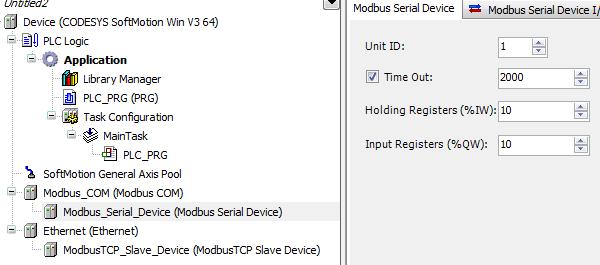
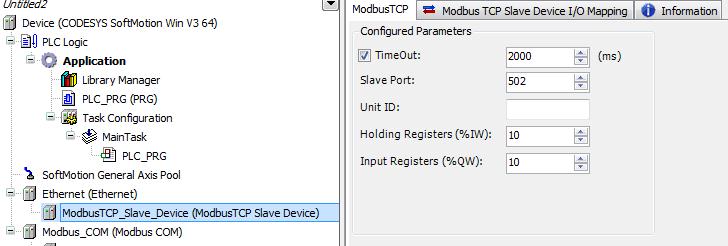
The project variables can be assigned to the holding and input registers in the … I/O Mapping tab. This procedure is exactly like in Master mode.
After performing all settings, simply connect the secondary devices to the SPK207 (master mode) or the SPK207 to the master device (slave mode), and check that the data exchange is correct.
The Modbus settings for the SPK207 are complete.

