akYtec developed a control system for a client's site, which manages water levels in tanks and includes remote control of a deep well valves with online water meter readings. The main control offers manual and automatic modes based on water levels. This system improved efficiency, reduced labor costs, and provided real-time monitoring with SCADA system and control capabilities.

From akYtec's range, we utilized the following components:
- PR103
- SMI200
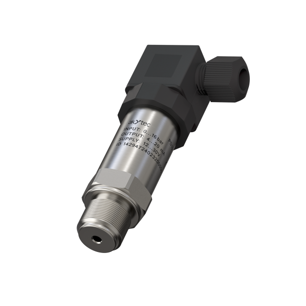
- PD100 (pressure)
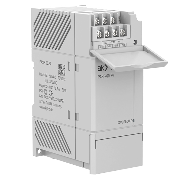
- PASF-60.24
Additional elements included:
- Button
- Level sensor
- Alarm siren
- Light
- Valves
- SCADA system

Controller I/O Terminal Assignments:
- I1: Connection for the external button to start manual mode.
- AI1: Level sensor.
- AI2: Pressure sensor on input.
- AI3: Pressure sensor on output.
- Q1: Manual mode selected, LED.
- Q2: Automatic mode selected, LED.
- Q5: Input pressure out of range.
- Q6: Alarm.
- Q7: Output pressure too high.
- AO1: Input valve.
- AO2: Output valve.
This PLC program manages a water system by switching between manual and automatic modes (Q1) to control water levels and pressures. It uses sensors to monitor these parameters (AI 1…3) and adjusts valves accordingly (AO 1 and 2) to maintain optimal conditions.
Alarms are set to alert (Q 5…7) if pressures exceed safe ranges, ensuring efficient and safe operation of the water system. The program is designed for real-time monitoring and control, enhancing system reliability and responsiveness.
Yellow section : Is meant for mode selection indication. When user activates manual mode (Variable “Mode switch” =1), “Automatic mode active” LED turns OFF (Variable “Automatic mode active”=0) and “Manual mode active” LED starts blinking ( Variable “Manual mode active”) indicating that system is manually controlled.
Orange section: Is for setpoint selection. If system is in automatic mode, then water level setpoint is predefined, but if user activates manual mode system will target “Manual setpoint” value, which is set over SMI200.
Red section: Is for indicating (over signal lamps) and alarming (over siren) if any pressure of input/output valves is out of range. Tripping setpoints are defined inside ALP and can not be modified by user for safety purpose.
In addition, ALARM signals are collected and sent to the SCADA system through Ethernet which was the key request from the user.
Green and Blue sections: Here PID blocks can be found, which are responsible for stable control of input/output valves for water filling. PID inside green block is controlling input valve (trying to reach water level setpoint), while the PID inside blue section is controlling output valve (trying to reach lower setpoint). This way, system always has water deposit in the tank, while ensuring constant water flow through output pipe.
This project involves the development of a control system designed to manage water levels in tanks using mini PLC technology. The control system includes remote control of deep well valves and provides real-time water meter readings. The system operates in both manual and automatic modes, enhancing efficiency, reducing labor costs, and providing real-time monitoring and control capabilities through a SCADA system. The control system features a water tank, pressure sensors, pipes, valves, a control block with PR103 as the main part, and a water level sensor.
The PR103 controls the overall operation, supported by the SMI200 for manual setpoint adjustments and PD100 pressure sensors for monitoring input and output pressures. The PASF-60.24 provides necessary power supply.
The system diagram illustrates various sections. The Mode Selection section includes a manual mode activated LED and an automatic mode active LED. The mode switch toggles between manual and automatic modes, with the manual mode LED blinking when active and the automatic mode LED turning on during automatic operation.
In the Setpoint section, water level setpoints can be defined. In automatic mode, the setpoint is predefined, whereas in manual mode, it targets a user-defined manual setpoint adjustable via the SMI200. The Alarm section is designed to indicate and trigger alarms if input or output pressures exceed safe ranges. It includes indicators for when the pressure is too high or when the input pressure is out of range. These alarms are also sent to the SCADA system via Ethernet for real-time monitoring and alerts, which was the key request from the client, thus PR103 was the only logical choice.
Input and Output Control sections use PID controllers to manage the input and output valves. The input control PID maintains the water level at the setpoint, while the output control PID ensures a constant water flow through the output pipe, maintaining a lower setpoint. This setup ensures a stable water deposit in the tank while providing consistent water flow.
The control system's software manages the water system by switching between manual and automatic modes, using sensors to monitor water levels and pressures. The sensors connected to the system include a level sensor for water level detection, a pressure sensor on the input pipe, and a pressure sensor on the output pipe. These sensors provide real-time data to the PLC, which adjusts the valves to maintain optimal conditions and sets alarms if pressures exceed safe limits.
Manual mode can be activated via an external button, and the system will display the current mode using LEDs. The manual mode LED blinks when manual mode is active, and the automatic mode LED illuminates when the system is in automatic mode. Alarms are crucial for safe operation, and the system includes several alarms for various conditions. If the input pressure is out of range or if the output pressure is too high, the system triggers alarms and activates the corresponding LEDs. The system also sends these alarm signals to the SCADA system for immediate action and monitoring.
The inclusion of analog outputs, with their programmability as their key property, in this device enables the control of various components such as valves, enhancing the system's versatility and functionality. Additionally, the use of universal analog inputs in the PR103 allows for the connection of a wide range of sensors, making the circuit adaptable to various sensing requirements.
Overall, this real-time monitoring and control system enhances reliability and responsiveness, ensuring efficient and safe operation. By providing a comprehensive solution for water level management, this PLC-based control system significantly improves operational efficiency and safety.
akYtec products used in the project