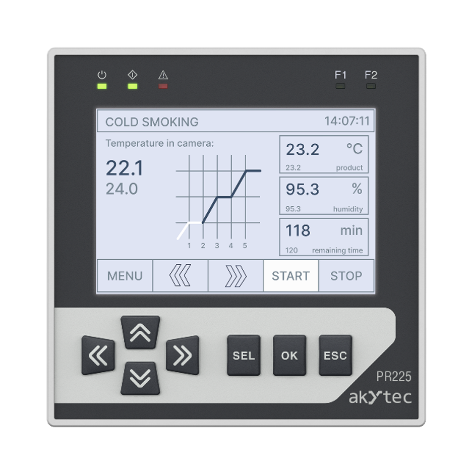
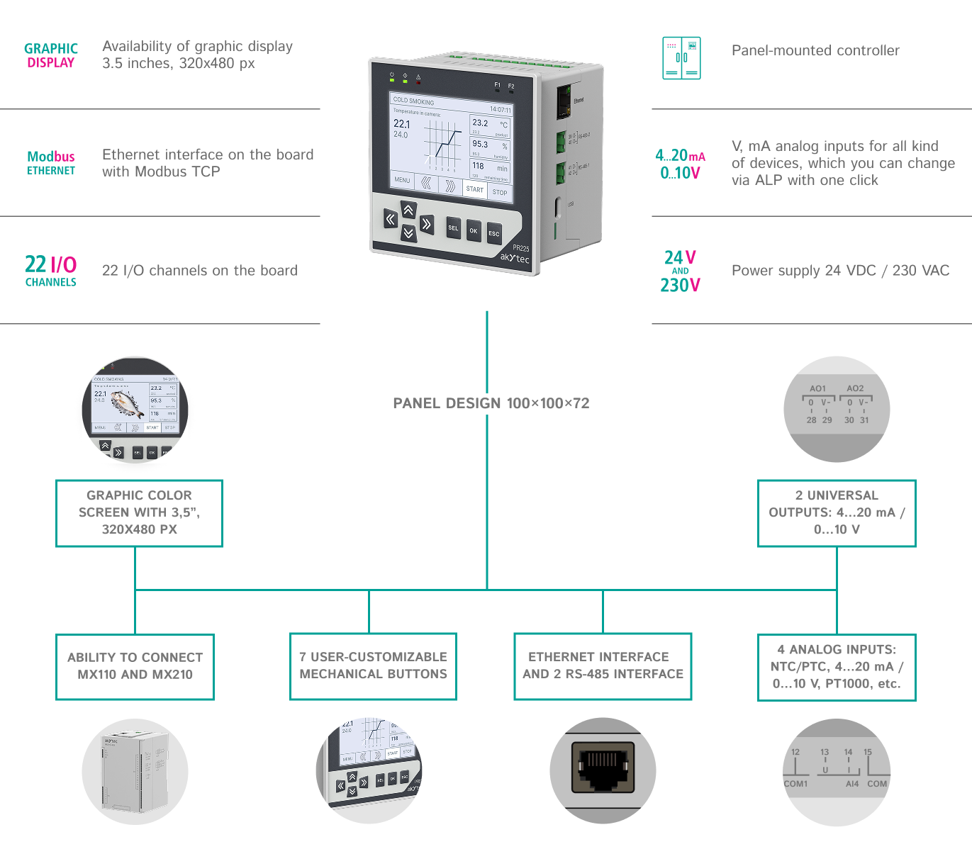
- Graphical color screen, 3.5" diagonal, 320×480.
- 7 mechanical buttons with user customizable.
- 5 LEDs: 3 service, 2 user.
- 4 analog inputs: PT1000, NTC/PTC, 4...20 mA/ 0...10 V, discrete mode.
- 2 universal analog outputs: 4...20 mA/0...10 V.
- 8 digital inputs (power supply =24 V / 230 V).
- 8 digital outputs (E/M relays and transistor keys).
- Direct access to akYtec cloud service.
- Connection to PC for program configuration and recording.
- Configuration in akYtec ToolPro.
- Process visualization with operator panels and SCADA.
- Increase of I/O with Mx210 modules.
- Integration into SCADA systems.
- Process visualization with operator panels.
- Increase of inputs/outputs by means of Mx110 modules.
- Control of external devices: VFDs, sensors, etc.
- Connection to PC for configuration and program recording.
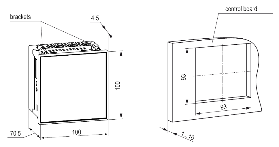
- Panel design 100×100×72
- Removable terminal blocks for easy installation.
- Quick battery replacement.
- IP front panel - IP54.
- 2 power supply modifications: ~/=24 and ~230 V.
- Operation in unheated premises: -20...+55 °С.
- Configuration and program recording via USB, Ethernet.
PR225 is a new programmable relay in a panel enclosure with a graphic display and Ethernet. The device combines an optimal configuration of analog and discrete inputs and outputs for control in water supply, heating, air conditioning, ventilation, food industry, and other systems.
The 3.5" color graphic screen allows you to create convenient and intuitive user interfaces, which greatly simplifies configuration and information perception. And mounting the device on the cabinet door does not require the use of an operator panel.
The Ethernet interface allows the device to be integrated into distributed systems, increase the number of inputs and outputs using Mx210 I/O modules, and remotely monitor and control equipment using the akYtec Cloud service. PR225 has 2 RS-485 interfaces. This allows the system to be expanded using Mx110 modules to control actuators or transfer data to the upper level.
The PR225's operating algorithm is built by the user in the absolutely free native programming environment akYtec ALP. This allows you to create unique user algorithms and take into account all the features of the system. This allows to create unique user algorithms and take into account all peculiarities of the system.
Variants
| PR225.24.2.2 | Panel-mounted 3.5” controller, 24 V DC, 8DI + 8DO (8 Relay) + 4AI + 2AO, 2x RS485 (Modbus RTU/ASCII), Ethernet (Modbus TCP) |
| PR225.230.2.2 | Panel-mounted 3.5” controller, 230 V AC, 8DI + 8DO (8 Relay) + 4AI + 2AO, 2x RS485 (Modbus RTU/ASCII), Ethernet (Modbus TCP) |
|
Naming |
PR225.X.2.2 |
|
Programming |
|
|
Programming software |
akYtec ALP |
|
Retain memory |
2040 bytes |
|
Stack |
Dynamic |
|
Network variable memory size (Slave mode) |
2040 bytes |
|
Number of network requests (Master mode) |
192 |
|
Memory ROM |
320 KB |
|
Memory RAM |
64 KB |
|
Programming interface |
USB Type-C, Ethernet |
|
Programming language |
FBD + support of function blocks on ST |
|
Language support in the application |
English, German |
|
Flash memory (archive) |
|
|
Number of write and erase cycles |
100 000 |
|
Maximum archive file size |
2048 bytes |
|
Maximum number of archive files |
50 pcs. |
|
Minimum archive recording period |
30 sec. |
|
General specifications |
|
|
Power supply |
20...36 V (nominal = 24 V) |
|
Power consumption, max. |
10 W / 15 VA |
|
Minimum cycle time |
1 ms (depends on program complexity) |
|
Real Time Clock |
Backup 5 years (CR2032) |
|
Expansion modules PRM |
No |
|
Digital inputs (DI) |
|
|
Quantity |
8 pcs |
|
Type |
Switch contact |
|
Connectable sensors |
Switching devices (buttons, switches, reed switches, relays), |
|
Logical states: 1 0 |
9...30 V DC (2…15mA) / 164…264 V AC (0.4…15mA) -3...+5 V DC (0...1.5mA) / 0…40 V AC (0…0.5mA) |
|
Galvanic isolation |
group of 4 inputs |
|
Electrical insulation strength |
510 V |
|
Analog inputs (AI) |
|
|
Quantity |
4 |
|
Measured signal types |
4...20 mA, 0...10 V, Pt1000, NTC, PTC, 0...300 kOhm, etc. |
|
Maximum refresh rate of input values |
1 ms |
|
Discrete mode operation |
Yes |
|
Galvanic isolation |
none |
|
Digital outputs (DO) |
|
|
Number of outputs |
8 |
|
Types of outputs |
Relay (normally open) |
|
Maximum permissible load |
|
|
Relay output |
5 А at a maximum voltage of 250 V AC cos(φ) > 0,95; 3 А at a maximum voltage of 30 V DC |
|
Transistor [switch] output |
0,5 А at a maximum voltage of 40 V DC |
|
Galvanic isolation |
|
|
Relay output |
Individual |
|
Transistor [switch] output |
None |
|
Isolation voltage rating |
|
|
Relay output |
2300V |
|
Transistor [switch] output |
None |
|
Analog outputs (AO) |
|
|
Quantity |
2 |
|
Analog output type |
Universal: 4...20 mА/0...10 V |
|
Resolution DAC |
12 bit |
|
Galvanic isolation |
4...20 mA output: individual 2830 V |
|
Permissible load |
12...30 V, max. 1 kohm |
|
Communication |
|
|
RS-485 interface (up to 2 pcs. selectable) |
|
|
Protocols |
Modbus RTU / ASCII (Master / Slave) |
|
Baud rate |
9.6...115.2 kBit/s |
|
Ethernet interface (1pc) |
|
|
Protocols |
Modbus TCP (Master / Slave) |
|
Baud rate |
10/100 Mbit/s |
|
Display and control |
|
|---|---|
| Display type | Graphic (IPS LCD) |
| Number of colors displayed | 65535 |
| Diagonal | 3,5“ |
| Resolution | 320 × 480 px |
| Supported languages | English, German |
| Function keys | 7 mechanical buttons (with program user customization) |
| LEDs | 3 service diodes, 2 with possibility of user customization |
| Environment | |
| Ambient temperature | -20...+55 °C |
| Storage temperature | -25...+55 °C |
| Humidity | up to 80% (non-condensing) |
| IP front panel | IP54 |
| IP Code | IP20 |
| Enclosure | |
| Dimensions | Panel version 100×100×72 mm |
| Weight | ca. 400 g |
| Material | plastic |

| Sensor | Measuring range |
|---|---|
| RTD according to IEC 60751:2008 | |
| Pt500, Pt1000 | -200…+850°C |
| Cu500, Cu1000 | -50…+200°C |
| Ni500, Ni1000 | -60…+180°C |
| RTD according to GOST 6651 | |
| 500P, 1000P | -200…+850°C |
| 500M, 1000M | -50…+200°C |
| Thermistors / NTC | |
| B57861S series, 2 kΩ, B25/100 = 3560 | -55…+100°C |
| B57861S series, 3 kΩ, B25/100 = 3988 | -55…+145°C |
| B57861S series, 5 kΩ, B25/100 = 3988 | -35…+145°C |
| B57861S series, 10 kΩ, B25/100 = 3988 | -35…+155°C |
| B57861S series, 30 kΩ, B25/100 = 3964 | -20…+155°C |
| B57861S series, 50 kΩ, B25/100 = 3760 | -10…+155°C |
| NTC 3435, 10 kΩ | -40…+105°C |
| NTC 3977, 10 kΩ | -40…+125°C |
| Thermistors / PTC | |
| KTY82-110 | -55…+150°C |
| KTY82-120 | |
| KTY82-121 | |
| KTY82-122 | |
| KTY82-150 | |
| KTY82-151 | |
| Standart signals | |
| 0-10 V 4-20 mA |
0...100% |
| Resistive signal | 0-300 kOhm | 0...100% |

