Welcome to akYtec!
 
Call us now: +49 (0) 511 / 16 59 672-0

ITP14 Universal Process Indicator 0-10 V / 4-20 mA

SKU: ITP14

The ITP14 is a versatile process indicator designed for monitoring and controlling industrial processes. This display features a configurable analog input and a digital output, enabling ON/OFF control functionality. The ITP14's compact and standardized design fits into a standard 22.5 mm borehole for signal lamps, allowing for quick and straightforward installation.

Main features of ITP14

  • Analog Input: Accepts 0-10 V or 4-20 mA signals.
  • ON/OFF Control: Includes an NPN output for ON/OFF control functionality.
  • Signal scaling.
  • Alarm Function: Features blinking alerts when setpoints are exceeded.
  • Adjustable decimal point position.
  • Access protection.
  • Standardized Design: Fits into a standard 22.5 mm borehole for signal lamps.

LED color0-10 V input4-20 mA inputNPN-transistor output (400 mA, 42 V DC)ON/OFF controlpower supply 24 V DCGalvanic isolationØ22.5 mmeasy mounting in a Ø22.5 mm holequick mountingcompact designthe process display can be installed into a push-button boxaccuracy 0.2%Character height 14 mmAmbient temperature

* Required Fields

- +
Product Description
    Details

    The ITP14 is a universally-applicable process display for monitoring and control of industrial processes. This device has a compact, standardised design and fits into a standard 22.5 mm borehole for signal lamps. This provides quick and easy installation and many displays can be accommodated in a control cabinet door or on a panel.

    This display features a digital output and a configurable analog input. The input can be set either for voltage signals (0-10 V and others) or for current signals (4-20 mA and others). Before displaying, the input signal is scaled and can be filtered if needed. There is also an optional square root function available. The NPN transistor output can control a load up to 42 V DC / 200 mA, which makes it possible to implement ON/OFF control. This output can also be used as an alarm output.

    The process indicator ITP14 also supports an alarm function. If this function is on, the display starts blinking with the frequency of about 2 Hz when the process value exceeds the set points.

    The device requires 24 V DC power supply. The enclosure can be operated in the temperature range between -40 and +60 °C.

    Functions and features:

    • - Analog input 0-10 V, 4-20 mA and others
    • - Measuring and displaying of the process value
    • - Signal scaling
    • - Adjustable decimal point position
    • - Display range -999…+9999
    • - ON/OFF control with an NPN output
    • - Square root function (for special transmitters)
    • - Digital filter
    • - Alarm function (blinking when exceeding the set points)
    • - Error indication when exceeding the measuring limits
    • - Error indication when wire break or short circuit

    Areas of application:

    The universal display ITP14 is particularly suitable for the fast and easy installation of visual display systems for various processes, such as water supply, thermal processing, and many other. The ITP14's compact size ensures that it can be used on-site as an additional display unit for measurement values or as part of a complex visual display system.

    Power supply 24 (10…30) V DC
    Power consumption, max. 1 W
    Input 1
    Input signal 0(2)-10 V, 0(4)-20 mA, 0-5 mA
    Sampling time 0.3 s
    Accuracy ±(0.2% FS + 1 digit)
    Temperature influence ≤ 0.2% / 10 °C
    Input resistance
    0-5 mA, 0(4)-20 mA ≤ 120 ohm
    0(2)-10 V ≥ 250 kohm
    Output 1
    Type NPN transistor
    Loading capacity 200 mA, 42 V DC
    Enclosure for panel mounting
    Character height 14 mm
    Dimensions 48 x 26 x 65 mm
    Weight approx. 30 g
    Ambient temperature -40…+60 °C
    Protection class III
    Relative humidity up to 80% (at +35 °C, non-condensing)
    FEEDBACK
Additional Information
FAQ

    FAQ

    What type of signal does the Universal Process Indicator ITP14 support? How should I connect it?

    The ITP14’s input can be set up to any of the following signal types:

    current: 0-5 mA, 0-20 mA or 4-20 mA

    voltage: 0-10 V or 2-10 V.

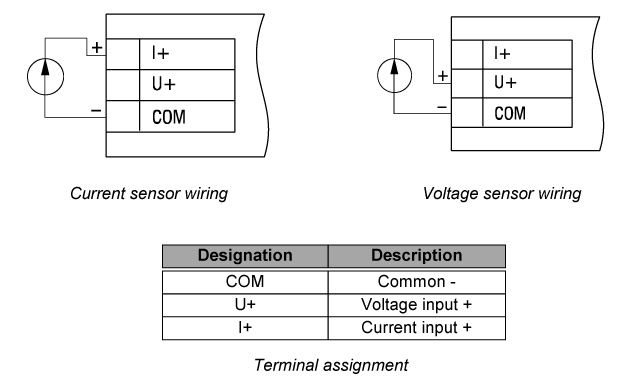
    The way you should connect your sensor to the ITP14 depends on the output signal of this sensor:

    Universal Process Display 4-20 mA / 0-10 V connection
    Rate the answer?
    Can I connect the ITP14 to an analog 4-20 mA or 0-10 V output directly?

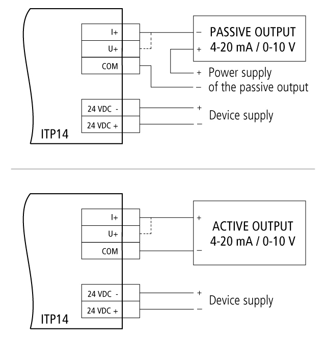
    That depends on the output, whether it is a passive or an active one.

    For example, the analog outputs of our Programmable Relay PR200 are passive outputs, meaning that any of them requires an external voltage.

    In case of an active analog output, no external voltage source is required.

    4-20 mA / 0-10 V connection to a passiver/active output

    Please note, the ITP14 must be powered by 24 V DC in both cases.

    Rate the answer?
    Can I connect several Process Indicators ITP14 to the common analog output? How should I connect them, in series or in parallel?

    Yes, you can do this.

    The connection depends on the input signal:

    Current (4-20 mA, 0-5 mA or 0-20 mA) – serial connection; the maximum number of displays depends on the available power, each ITP14 consumes 1W;

    Voltage (0-10 V or 2-10 V) – parallel connection; the maximum number of displays depends on the available load current.

    Rate the answer?
    I have connected the ITP14 but it doesn’t switch on, what should I check?

    The ITP14 requires an auxiliary voltage of 24 V DC, so please ensure you have provided it.

    If the display still doesn't function, check if the polarity of the voltage connection is correct.

    Check the wiring. A wire may be loose or not connected to the corresponding terminal.

    Rate the answer?
    Can I connect a 0-20 mA signal to an ITP14? What about a 0-10 V or a Pt100 signal?

    Yes, you can connect all these signals to an ITP14, except the Pt100 signal. We can offer you the Temperature Display ITP16 for the purpose of connecting a Pt100 signal.

    Please feel free to contact us if you need support.

    Rate the answer?
    What voltage does the ITP14 require?
    The Universal Process Indicator ITP14 requires 24 (10…30) V DC.
    Rate the answer?
    What software do I need to program the ITP14?

    You don’t need any software for programming the ITP14. The programming is carried out by using three buttons on the ITP14’s cylindrical body.

    Rate the answer?
    Should I program the display before or after the installation?
    Technically, it doesn't matter; but in terms of convenience, it depends on your particular case.
    Rate the answer?
    Can I switch on/off the output of the ITP14 depending on the signal value at its input?

    Yes, you can do this.

    You have to specify the required setpoints and select the required control function. For this purpose, proceed as follows:

    • - Connect the device to a 24 VDC power supply
    • - Access the parameter menu: Hold down the PROG button for at least 3 seconds
    • - Set the setpoints: Find the parameter ‘SP.Lo’ by navigating the menu with the UP or DOWN button (these same buttons are used to increase/decrease the value of any selected parameter). Press PROG and set the required value for the lower setpoint limit. Press PROG once again to save the value and exit. Set the required value for the upper setpoint limit (‘SP.Hi’) in a similar way
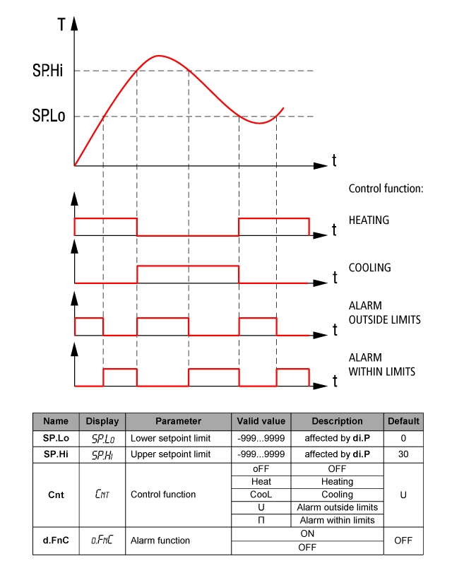
    • - Select the control function: Find the parameter ‘Cnt’, press PROG and select the required control function (see the figure below). Press PROG once again to save the value and exit.
    Control functions of the ITP14 Universal Process Display 4-20 mA / 0-10 V

    Additionally, you can make so that the display will blink when the output is ON. Just find the parameter ‘d.FnC’ in the parameter menu, press PROG, select ‘ON’ and press PROG again to save the value and exit.

    To exit the parameter menu, hold down PROG for at least 3 seconds.

    Rate the answer?
    If I need to show a percentage value, what should the measuring limits be?

    The lower measuring limit (the parameter di.Lo) should be set to 0.

    The upper measuring limit (the parameter di.Hi) should be set to 100.

    Rate the answer?
    How can I scale the measuring limits of the ITP14?
      To scale the measuring limits, please proceed as follows:

    • - Connect the device to a 24 V DC power supply
    • - Access the parameter menu: Hold down the PROG button for at least 3 seconds
    • - Set the measuring limits: Find the parameter ‘di.Lo’ by navigating the menu with the UP or DOWN button (these same buttons are used to increase/decrease the value of any selected parameter). Press PROG and set the required value for the lower measuring limit. Press PROG once again to save the value and exit. Set the required value for the upper measuring limit (‘di.Hi’) in a similar way.

    To exit the parameter menu, hold down PROG for at least 3 seconds.

    Rate the answer?
    What is the alarm function? How can I use it?

    The alarm function makes the display blink with a frequency of about 2 Hz when the output is switched on.

    To use this function properly, please proceed as follows:

    • - Connect the device to a 24 VDC power supply
    • - Access the parameter menu: Hold down the PROG button for at least 3 seconds
    • - Switch on the alarm function: Find the parameter ‘d.FnC’ by navigating the menu with the UP or DOWN button (these same buttons are used to increase/decrease the value of any selected parameter). Set this parameter to ‘ON’, press PROG once again to save the value and exit.
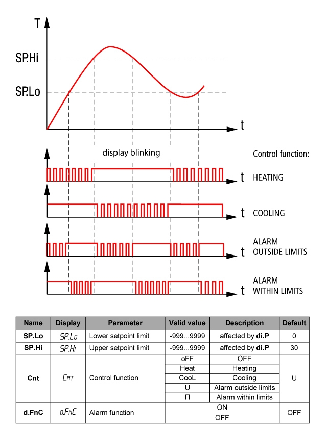
    • - Select the control function: Find the parameter ‘Cnt’, press PROG and select the required control function (see the figure below). Press PROG once again to save the value and exit.
    • Alarm functions of the ITP14 Universal Process Display 4-20 mA / 0-10 V
    • - Set the setpoits: Find the parameter ‘SP.Lo’, press PROG and set the required value for the lower alarm limit. Press PROG once again to save the value and exit. Set the required value for the upper alarm limit (‘SP.Hi’) in a similar way.

    To exit the parameter menu, hold down PROG for at least 3 seconds.

    Rate the answer?
    What is the IP rating of this display?

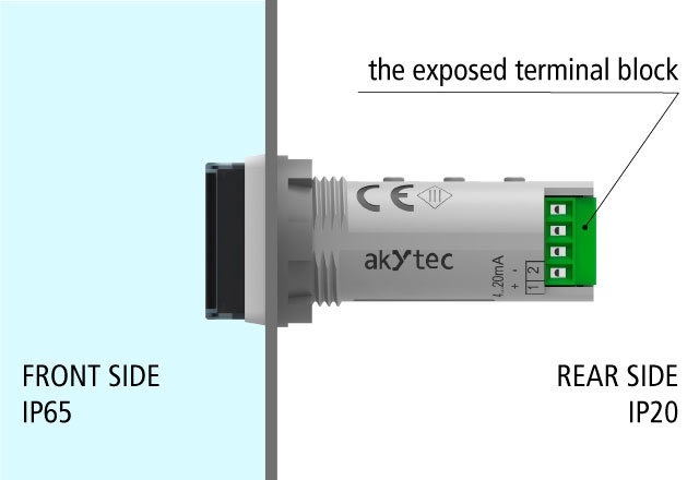
    Proper device installation (see User Guide) warrants protection against dust and water (IP65 on the front). Because of the exposed terminal block, the rear part of the enclosure is rated much lower – IP20.

    Process display 4-20 mA IP rating
    Rate the answer?
    In what colors is the display available?

    The enclosure is only available in grey color. The LEDs can be ordered in red or in green color.

    Rate the answer?
    What is the ITP14’s input resistance?

    The input resistance between the terminals:

    +I and COM is ≤ 120 ohm (current signals: 0-5 mA, 0-20 mA, and 4-20 mA)

    +U and COM is ≥ 250 kohm (voltage signals: 0-10 V and 2-10V).

    Rate the answer?
    What conductor cross section is permitted?

    The maximum cross section of a solid conductor is 0.2 – 0.8 mm².

    The maximum cross-section of a stranded conductor is 0.45 – 0.7 mm².

    Rate the answer?
    What is the ITP14’s accuracy? What about its sample time?
    The accuracy is 0.2 % FS + 1 digit. The sample time is 0.3 s.
    Rate the answer?
    Is the ITP14 protected against overload? What about reverse polarity protection?

    There is no overload protection at the ITP14’s power supply input, so please ensure that the power supply doesn’t exceed 30 V.

    In case of wrong polarity, the device won’t operate, but it won’t be damaged either.

    Rate the answer?
    Is there any galvanic isolation between the input, the output, and the voltage supply circuit?

    The ITP14 or the ITP14, each of them has three potential groups:

    • − Power supply 24 V DC
    • − Analog input
    • − Digital output

    Galvanic isolation from each group to the enclosure is 500 V.

    Galvanic isolation between groups is 500 V.

    Rate the answer?
    What diameter should the mounting cutout be to install this display?
    The device is designed for panel mounting in a borehole of Ø22.5 mm (see User Guide, Appendix A).
    Rate the answer?
    What is the maximum distance to connect a 4-20 mA signal to the ITP14?

    The maximum recommended distance to connect a 4-20 mA to the ITP14 is 100 m. However, we recommend keeping it as close as possible to the signal source because the resistance of a long conductor can affect the measurement accuracy.

    Rate the answer?
    Do you have an ePLAN 3D model of this display?

    The ePLAN 3D model is available under the tab ‘DOCUMENTS AND SOFTWARE’ on the product page. There is also a STEP model available under the same tab.

    Rate the answer?
    Can I set di.Low=0 and di.High=25 so that if input voltage of 0V corresponds to 0 and 10V corresponds to 25 ?
    Yes, if you set the parameter di.Lo to 0, it will correspond to 0 V and if you set the parameter di.Hi to 25, it will correspond to 10 V.
    Rate the answer?