Welcome to akYtec!
 
Call us now: +49 (0) 511 / 16 59 672-0

PR200 programmable relay

SKU: PR200
The programmable relay PR200 is a universal and easy-to-use device designed in a plastic enclosure for DIN rail mounting as an alternative to PLC. The relay is available in several versions, for DC and AC voltage, equipped with only digital or a combination of digital and analog inputs and outputs.

8 digital inputsup to 8 digital outputsup to 4 analog inputsup to 2 analog outputsLCD displayModbus RTU/ASCIIRS485 interfaceUSB interfacebuilt-in real-time clockDIN rail mountingsoftware at no chargeAmbient temperature

* Required Fields

- +
Product Description
    Details

    The programmable relay PR200 is a universal and easy-to-use device designed in a plastic enclosure for DIN rail mounting as an alternative to PLC. The relay is available in several versions, for DC and AC voltage, equipped with only digital or a combination of digital and analog inputs and outputs.

    The device has a 2-line 32-character LCD display. A real-time clock and up to 2 RS485 interfaces for connection to Modbus networks are available. The relay can be expanded with additional I/O-Modules (for example, our modules of Mx110 series).

    The PR200 is programmed in the easy to use akYtec ALP software (available free of charge) using standard FBD programming language (IEC 61131-3). This software offers a library of many function macros and also allows creating your own macros. In addition, there are also available simulation mode and a complete overview of resource usage. Once the application program is done, it can be transferred to the relay via mini-USB port on the device front panel.

    Other features of the programmable relay PR200 include:
    • Up to 8DI + 8DO + 4AI + 2AO + LCD + 2xRS485 in one device
    • Connecting different sensors 4-20mA, 0-10V, resistance-type (PTC, KTY thermistors, Pt1000) and actuators
    • Control of the outputs according to the input status and the logic of the user application
    • Configuration with the function buttons or using ALP software
    • Comprehensive programming of LCD display
    • 2 programmable LEDs
    • Master and / or Slave in a Modbus network
    • Real-time clock
    • Extension modules
    • Removable terminal blocks

    PR200 can be used in numerous applications such as building automation, lighting control and access control systems, technical equipment such as pumps, fans, compressors and presses to conveyor and filling systems etc.

    Ordering information

    PR200 - X . X . X
    Supply voltage
    230 (94...264) V AC 230
    24 (19…30) V DC 24
    I/O
    8 DI, 6 DO 1
    8 DI, 4 AI, 8 DO, 2 AO (4-20 mA) 2
    8 DI, 4 AI, 8 DO, 2 AO (0-10 V) 4
    Interface
    none 0
    RS485 1
    2x RS485 2

    Variants

    PR200.24.1.1 24 V DC, 8DI + 6DO, LCD, 1x RS485 (Modbus RTU/ASCII)
    PR200.24.2.0 24 V DC, 8DI + 8DO + 4AI + 2AO (4-20 mA), LCD
    PR200.24.2.2 24 V DC, 8DI + 8DO + 4AI + 2AO (4-20 mA), LCD, 2x RS485 (Modbus RTU/ASCII)
    PR200.24.4.0 24 V DC, 8DI + 8DO + 4AI + 2AO (0-10 V), LCD
    PR200.24.4.2 24 V DC, 8DI + 8DO + 4AI + 2AO (0-10 V), LCD, 2x RS485)
    PR200.230.1.1 230 V AC, 8DI + 6DO, LCD, 1x RS485 (Modbus RTU/ASCII)
    PR200.230.2.0 230 V AC, 8DI + 8DO + 4AI + 2AO (4-20 mA), LCD
    PR200.230.2.2 230 V AC, 8DI + 8DO + 4AI + 2AO (4-20 mA), LCD, 2x RS485 (Modbus RTU/ASCII)
    PR200.230.4.0 230 V AC, 8DI + 8DO + 4AI + 2AO (0-10 V), LCD
    PR200.230.4.2 230 V AC, 8DI + 8DO + 4AI + 2AO (0-10 V), LCD, 2x RS485
    PR200.230.1 PR200.230.2 PR200.24.1 PR200.24.2
    General
    Power supply 230 (90...264) V AC;
    50 (47...63) Hz
    24 (19...30) V DC
    Power consumption, max. 10 VA 17 VA 10 W
    Integrated voltage source - 24±3 V DC 100 mA -
    Real Time Clock Backup 5 years (CR2032) Backup 5 years (CR2032)
    Display LCD with backlight, 2-line,
    2x 16-characters
    LCD with backlight, 2-line,
    2x 16-characters
    Function keys 6 6
    Programming
    Programming environment akYtec ALP akYtec ALP
    Programming language FBD FBD
    Programming interface Mini-USB Mini-USB
    ROM 128 kB 128 kB
    Retain memory 1016 Byte 1016 Byte
    Communication
    Interface card PR-IC485 (max. 2) PR-IC485 (max. 2)
    Interface RS485 RS485
    Protocols Modbus RTU / ASCII (Master / Slave) Modbus RTU / ASCII (Master / Slave)
    Baud rate 9.6...115.2 kBit/s 9.6...115.2 kBit/s
    Digital inputs
    Quantity 8 8
    Type Switch contact Switch contact
    PNP with open collector
    Digital signals -3...30 V DC
    Logical states 1 159...264 V AC (0.75...1.5 mA) 15...30 V DC (5 mA)
    0 0...40 V AC (0...0.5 mA) -3...+5 V DC (0...1 mA)
    Galvanic isolation in groups of 4 in groups of 4
    Universal inputs
    Quantity - 4 - 4
    Input signal - Analog / Digital - Analog / Digital
    Galvanic isolation none none
    Analog input - 4-20 mA, 0-10 V,
    0-4 kohm
    - 4-20 mA, 0-10 V,
    0-4 kohm
    Resolution ADC 12 bit 12 bit
    Digital outputs
    Quantity 6 8 6 8
    Type relay, NO relay, NO
    Galvanic isolation in groups of 2 in groups of 2
    Contact capacity AC 5 A, 250 V (resistive load) 5 A, 250 V (resistive load)
    DC 3 A, 30 V 3 A, 30 V
    Minimum load current 10 mA (at 5 V DC) 10 mA (at 5 V DC)
    Analog outputs
    Quantity - 2 - 2
    Analog outputs - 4-20 mA, 0-10V
    (for PR200.X.4)
    - 4-20 mA, 0-10V
    (for PR200.X.4)
    Permissible load - 12...30 V,
    max. 1 kohm
    - 12...30 V,
    max. 1 kohm
    Resolution DAC 10 bit 10 bit
    Environment
    Ambient temperature -20...+55 °C -20...+55 °C
    Storage temperature -25...+55 °C -25...+55 °C
    Humidity up to 80% (non-condensing) up to 80% (non-condensing)
    IP Code IP20 IP20
    Enclosure
    Dimensions 123 x 108 x 58 mm 123 x 108 x 58 mm
    Weight ca. 350 g ca. 350 g
    Material plastic plastic

    Temperature & Humidity Monitoring

    Monitoring of temperature and humidity is a very common automation task which can be easily solved by means of products from akYtec. A quick and cost-effective solution based on Programmable relay PR200 we have implemented in the sample project below:

    Project description

    Project file

    programmable relay

    Modbus communication between SMI200 and PR200. Sample Project

    Having gone through all the pages, you will answer the following questions by yourself:

    • - How to establish a successful communication between SMI200/PR200 and PC?
    • - How to make PR200 operate as Master, read some values (INT and REAL) from a Slave device (SMI200), and display them on its LCD?
    • - How to make SMI200 operate in the Master mode, read some values from a Slave device (PR200) in two ways – using network variables and directly from Modbus registers – and display them on its LCD?

    Product description


    Pump control

    There are two pumps in this project controlled by the programmable relay PR200. Their operation depends on the signal value from a temperature sensor and two set points. The values of the set points are received from a SCADA system that the PR200 is connected to via Modbus RTU. Both pumps can be stopped by an emergency stop button or through the SCADA system. The temperature values and the status of the pumps are shown on the PR200 display.

    Project description

    Project file

    programmable relay

    Press machine

    It is shown in this project how the programmable relay PR200 can be used to prevent the operator from accidental injuries when operating a press machine. In addition, there is implemented a counting function and its result is displayed on both the relay's display and the RS485 display SMI2 that is connected to the PR200 via Modbus. Moreover, there is also a testing mode available. For more details, please refer to the project description on the link below:

    Project description

    Project file


    Modifiable Week Clock

    Some automation tasks require switching on/off a secondary device according to a particular schedule. Schedules are often subject to change. With this sample project, you can learn how to set, and more importantly, to change the schedule of the output activity with the PR200's function keys and its screen. It means, there is no need to rewrite and re-upload your application.

    Moreover, there are used three macros from our Online Database (“Clock_Mod”, “Day_Week” and “Set value selector”) in this project, so it is a great opportunity to get familiar with them.

    Project description

    Project file


    Firmware version of the TRM202 on the LCD of the PR200

    The objective of this sample project is to provide an example of how string data can be read by the PR200 Programmable Relay and be shown on its LCD display. In this example, the String Data is the TRM202 firmware version that is stored in its Modbus registers. As Modbus Master, the PR200 is supposed to read the firmware string from the corresponding registers over the RS485 serial communication interface.

    Project description

    Project file


    We hope these projects will be very helpful and save your time significantly.

FAQ

    FAQ

    I have 2 self-written macros "Average" and "8 INT_M". If the macro "Average" is already used in a project, I cannot import the macro "8 INT_M" anymore. The message appears: The macro "8 INT_M" already exists... replace? Yes/No Why is it happening, and how can I import this macro?
    This happens because you are trying to import a macro with an already existing ID, though its name and content are different. Most likely, you created one macro, used the command ‘Export macro’, modified this very same macro, and then exported it with a different name. In this case, akYtec ALP assigned an inner ID for the first macro and never changed it even after you had used the Export macro command once again. To overcome this collision, you should have used the command ‘Save macro as…’ before exporting the second macro based on the first one.
    Rate the answer?
    Is it possible to connect Pt100 to PR200?

    There are two ways to connect a Pt100 sensor to the PR200 Programmable Relay:

    1. Use the Pt100 macro (see the attachment to this post)
    2. Use an analog input of the PRM-X.3 extension module.

    Although the first method is completely free to implement, it does not provide enough accuracy. The accuracy of ±5% (52,5 °C) may be too poor for some applications.

    If the accuracy is of the utmost importance to your project, the second method is the best solution for you. Having purchased a PRM-X.3, or if you already have one, you can configure any of its inputs for Pt100. In this case, accuracy is ±0.25% (2.6 °C). Since the extension modules of the PRM series are connected to the PR200 over an internal bus, the PR200 treats them as its own, meaning the I/Os of a PRM module are of the same performance as the I/Os of the base unit (PR200).

    Rate the answer?
    What software do I need to program the PR200? How much does it cost? Do I need a specialized cable?

    You need our programming software ‘akYtec ALP’. It is free of charge. You can find it either on our website or on the USB stick, which is included in the delivery.

    Yes, you need a cable (USB A-plug to micro B-plug), which is also included in the package.

    Rate the answer?
    Time Delay of RS485 datastream and analog output?

    The program execution time (cycle time) is automatically adjusted based on the program complexity (Auto-Tuning). The automatic adjustment affects the data exchange via Modbus since program execution takes higher priority over processing requests. If the program is very extensive, it can consume the entire CPU time, and the Modbus data exchange will not be carried out correctly.

    To avoid this issue, a lower limit is reserved for the volume of Modbus data exchange: 50 requests per second. This means that at least 50 requests per second can be executed, even if the user program is large, and even more if the program is small and the processor performance is sufficient. If there is not enough time to query all devices, the number of queries in the user program should be optimized.

    The setting of the polling cycle depends on the number of variables queried and the polling frequency in the program. It is recommended to set the polling cycle to 1 second. In this case, the device can query up to 50 variables.

    The minimum processing time of the program cycle is 1ms, and the signal conversion time for analog outputs is 100ms.

    Rate the answer?
    How can I change the parameters ‘Start date/time’ and ‘Stop date/time’ of the functional block ‘CLOCK WEEK’ from the front panel of the PR200 or through a variable in akYtec ALP?

    Since the ‘CLOCK WEEK’ does not have any inputs you cannot change the parameters of this functional block both from the front panel and through variables.

    If you need a modifiable ‘CLOCK WEEK’ in your project, two macros are available in the online macro database as well as a sample program that shows how these macros should be programmed.

    To download the sample program, please use this link, open and look for the sample project 'Modifiable Week Clock'.

    You may refer to the following video to see the instructions on how to download the macros:

    Rate the answer?
    Difference between PNP and Relais Output?

    The PR’s has relais outputs, Relay outputs use an electromagnetic coil to actuate a switching contact. When the control voltage is applied to the relay coil, it either closes or opens the switching contacts to control the load.

    Whereas PNP transistor outputs are commonly used in control circuits to switch electrical loads, such as relays, LEDs, or motors.

    They are e used to provide a positive voltage signal to turn on or control a connected load. When a positive voltage is applied to the base, the transistor becomes conductive, and the collector is connected to the emitter, allowing current to flow to the load.

    The main difference is that PNP transistor outputs represent an electronic method for controlling loads, while relay outputs are electromechanical devices. The choice between them depends on the specific requirements of the application and design preferences.

    Rate the answer?
    How can I change the parameters of a functional block (i.e. BLINK, TON, TOFF, TP) from the front panel of the PR200 or through a variable in akYtec ALP?

    To write to or read from a functional block, it is necessary to use the blocks 'WriteToFB' or 'ReadFromFB', respectively. You can find these blocks on the toolbar ‘Insert’.

    You may refer to the following video to see instructions on how to use these tools:

    Rate the answer?
    What is the maximum load capacity of the inputs and outputs?

    Digital Input: 264 V AC (for 230.x.x Version) 30VDC (for 24.x.x version)

    Digital Output: AC 5A, 250 V DC: 3A, 30V

    Rate the answer?
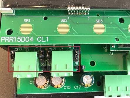
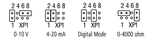
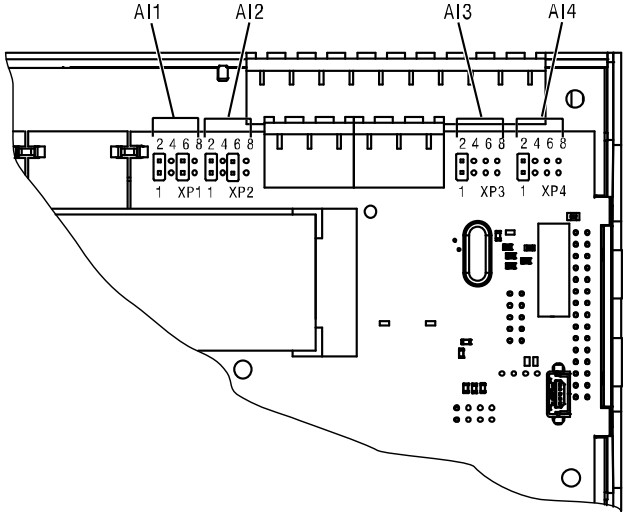
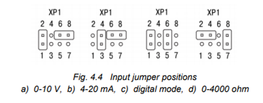
    How to change analog input between Resistance, Voltage (R, U, I)?

    To configure the input hardware: – remove the front cover – set the jumpers on the respective jumper block XP in accordance to the expected input signal using a thin tool (e.g. tweezers) – close the front cover.

    Input Jumper Positions
    Rate the answer?
    Can I expand the number of inputs/outputs of the PR200?

    The main and the simplest way to do it is to use the PRM Extension Modules from akYtec. With these modules, you can extend the PR200 by up to 16 additional digital inputs and up to 16 digital outputs. Alternatively, if your system requires more I/O-points, you can use Modbus RTU/ASCII and connect up to 32 expansion modules over the RS485 interface. We recommend using our I/O-Modules of the Mx110 series for this purpose.

    Rate the answer?
    Can the PR200 be used in a Modbus network as a slave?

    In general it is possible to use the PR200 in the slave mode but note:

    when a device is configured as a Modbus RTU Slave, it generally cannot accept unsolicited messages or write commands directly from the Master. The Slave can only respond to read requests (queries) from the Master. This means the Master can request data from the registers of the Slave (e.g., Holding Registers, Input Registers, Discrete Inputs), but the Slave will not actively send data or accept write commands from the Master.


    In the Slave mode, the following network functions are possible:


    • Read digital I/O status
    • Read analog I/O value
    • Read / write network variables
    • Read / write Real-Time Clock data


    To configure the PR200, you will need the akYtec ALP. ALP stands for the programming software for the PR200 and many other devices from akYtec. However, please note that the write function is limited to specific resources. Therefore, you should consider whether the PR200 is suitable as a Slave to meet your requirements. Also, it is advisable to ensure that the used Master device is compatible with the akYtec ALP to facilitate a smooth setup.

    Rate the answer?
    How can I connect an expansion module of the Mx110 series to the PR200?
    A module of Mx110 series can be connected to the PR200 via the RS485 interface and Modbus protocol.
    Rate the answer?
    Can I use the PR devices to control and monitor the current of my PV system?

    Yes, the PR-devices series can be used to monitor and control the consumption of a PV system. The PR series supports the Modbus RTU protocol, making it compatible with any energy meter that supports this protocol. The digital outputs of the series are suitable for control purposes and can, for example, redirect the current to a battery, the general power grid, or heating elements

    Rate the answer?
    What is the maximum permissible frequency that a digital input of the PR200 can handle in case of using this input to read an impulse signal?

    This frequency depends on the device variant.

    PR200-230.X.X:10 Hz

    PR200-24.X.X: 250 Hz.

    In either case, a square wave pulse signal with 50% duty cycle is assumed.

    Rate the answer?
    Loss of data. Do you lose the ALP program when you change the battery?
    The user program is written to the retain memory. The battery can be changed without any issues, and the program remains unaffected. It's worth noting that when the battery is replaced, the RTC will be reset. The battery typically lasts for about 8 years.
    Rate the answer?
    Are the relay outputs of the PR200 suitable to control a power contactor?

    It depends on the switching current of the power contactor. A relay output of the PR200 has the following switching capacities:

    AC: 5 A, 250 V (resistive load)

    DC: 3 A, 30 V. 

    Rate the answer?
    Compatibility with HMI? What does a HMI need to be working with the PR-devices?
    Any HMI device compatible with the Modbus RTU Protocol is of displaying process values and can be utilized as an HMI with the PR device series.
    Rate the answer?
    Can the integrated voltage source of a PR200-230.X.X be used for feeding an input module Mx110-24.X? What about feeding an ITP16 or ITP14?
    No, this voltage source cannot be used for feeding an Mx110 module because it doesn’t provide enough current (max. 100 mA). However, this current is enough for both an ITP display or its analog output.
    Rate the answer?
    What happens to my variables when we have a power failure? Is the program persistent?
    The program is stored in the retain memory, which remains unaffected in the event of a power failure. Therefore, in the event of a power failure, your PR device will retain the program and will not require reprogramming. Variables that must be stored in non-volatile memory must be marked as retain in the ALP project.
    Rate the answer?
    What is the minimum voltage and current needed for proper operation of an input of the PR200?

    It depends on the device variant:

    PR200-230.X.X: 159 V and 0.75 mA.

    PR200-24.X.X: 15 V and 5 mA.

    Rate the answer?
    Can the PR-Devices be used as a PID-Controller?
    Yes the PR-devices can function as PID-Controller, our ALP Software utilizes function block language and comes with preinstalled macros like PID Controller and PWM Generator, among others.
    Rate the answer?
    How many variables can the PR200 handle as Modbus Slave?

    It depends on the type of the variables. They can be either INT or REAL. An INT variable stores data in only one register, while a REAL variable requires two registers for this.

    Since the PR200 as Modbus Slave have only 64 registers, it means the maximum number of variables is:

    64 if you declare only INT variables

    32 if you declare only REAL variables.

    If there are both INT and REAL variables, you should calculate their maximum permissible number according to their combination. For example, if you declare 10 REAL variables, which is equal to 20 INT variables, you can declare up to 44 INT variables (64 - 20 = 44).

    Rate the answer?
    Can I control a pumping System with the PR-devices?

    Yes, the PR-Devices can be used to control pumping systems. Therefore, we recommend exploring the sample projects available on our website. We also offer sample projects that showcase the capabilities of PR devices, such as a press machine.

    In one of these projects, we demonstrate how the programmable relay PR200 can be utilized to enhance operator safety when operating a press machine. Additionally, a counting function has been implemented, and its results are displayed.

    Another example project involves a modifiable week clock. Some automation tasks require toggling secondary devices based on specific schedules, which can change over time. With this sample project you can learn how to set more importantly, modify the schedule of output activities using the PR’s function keys and screen.

    Rate the answer?
    How many Modbus Slaves can the PR200 control as Master Device?
    The PR200 as Modbus Master can control up to 16 Slave Devices over each RS485 interface. Each Slave Device can process up to 256 variables.
    Rate the answer?
    What steps do I have to take to calibrate the PR-devices when i have uncertanties in the measurement?

    If the accuracy of the input or output of the module is no longer in accordance with the specification, it can be calibrated.

    Each analog input and output has its own calibration coefficients for each sensor type.

    – The calibration is performed using a reference signal source connected to the device input or output.

    – The calibration coefficients are calculated based of the ratio between the current input signal and the reference signal and stored in the non-volatile device memory.

    – If the calculated coefficients go beyond the permissible limits, a message about the error cause will be displayed.

    For further concrete instructions on page 36 in the manual shows step by step instructions on how to calibrate input/ or output

    Rate the answer?
    I have a PR200 with 2 RS485 interfaces. Is it possible to read some data from a Modbus Slave Sensor over one RS485 and make them available on the other?

    Yes, this application is possible.

    You need two network variables, one per interface. Then you just link them by means of the tools ‘Network variable input block’  and ‘Network variable output block’ . For step-by-step instructions, please watch this video:

    Rate the answer?
    How to display negative values on the display?
    Only positive INT values can be stored in the Modbus registers. Positive values in the range of 0 to 32767 are stored as usual. To write a negative number in Modbus registers, you need to add 65536 to that number. For example, the number – 1 corresponds to 65535 in Modbus registers and -100 corresponds to 65436. In Akytec ALP you can find the INT16 macro in the component manager, which performs this conversion and outputs either an INT or a REAL value.
    Rate the answer?
    I have set Slot 1 to Master on the Device Configuration dialog box in akYtec ALP but it doesn’t work properly. What should I check?

    First of all, this problem can be caused by a wrong position of jumpers. There are two jumpers, XP4 and XP5, on the RS485 interface card of the PR200. They can be set either to Master or to Slave:

    Positions of jumpers

    By default upon delivery, they are set to Slave. To use the interface as Master, the jumpers must be set to the M position:

    Interface cards

    If the jumpers are set to Master and the communication problems still occur, you should check if:

    - all the devices on the network have the same network parameters (protocol, baud rate, parity, stop bits and data bits)

    - there is only one Master (in this case the PR200) on the network

    - all wires are connected properly and there are no loose wires

    - signal cables are screened or routed separately from power cables

    - the secondary devices on the network are connected to the PR200 in a linear (bus) topology, meaning each device is directly connected to a common line (the bus), and all signals are transmitted from one end to the other

    - there are terminating resistors at both ends of the communication bus. Experience shows that the most efficient practice is to use terminating resistors of 150 ohm.

    Rate the answer?
    How does the Modbus register work and why is it in hexadecimal? (3x0000 to 3xFFFF)

    Modbus registers work as a way to store and exchange data in Modbus communication, which is a popular protocol used in industrial automation and control systems. Modbus registers are typically 16-bit values, and they are indeed represented in hexadecimal format. Here's an explanation of how Modbus registers work and why hexadecimal is used:

    1. Data Storage: Modbus registers are used to store various types of data, such as sensor readings, control parameters, status information, and more. These registers are organized in a range from 0x0000 to 0xFFFF, which covers 65,536 possible values.
    2. 16-Bit Format: Each Modbus register is 16 bits (2 bytes) in length. This means that it can hold values ranging from 0 to 65,535. The 16-bit format is common in industrial control systems because it provides a good balance between precision and data size.
    3. Hexadecimal Representation: Hexadecimal (base-16) is used to represent Modbus registers for several reasons:
      • Compactness: Hexadecimal allows for a compact representation of binary data. Each hexadecimal digit represents four binary bits, making it efficient for displaying and working with 16-bit values.
      • Human Readability: Hexadecimal is more human-readable than binary or decimal for 16-bit values. It uses the digits 0-9 and the letters A-F to represent values from 0 to 15.
      • Alignment: Hexadecimal values align neatly with bytes. In a Modbus register, each byte is represented by two hexadecimal digits, making it easier to work with when dealing with byte-oriented communication protocols.
      • Consistency: Hexadecimal is consistent with the way data is often displayed and configured in industrial control systems and related software.
    4. Addressing: The "3x" in "3x0000 - 3xFFFF" refers to the Modbus function codes. In Modbus, function codes 3 and 4 are used for reading and writing registers. The "x" in "3x" signifies that these registers are in the "holding registers" category. Holding registers are used to store data that can be read and written by external devices
    Rate the answer?
    In what numeral system should be written the register address, decimal or hexadecimal?
    The register address has to be written in decimal.
    Rate the answer?
    I have connected a slave device to the PR200. I can read INT variables but I am having problems with REAL variables. I want to show a value on the display but it shows a different value that doesn’t make sense. What should I check?

    To read and show REAL variables, it is important to know the endianness of the registers and bytes, i.e. register and byte ordering. It can be either big-endian or little-endian format.

    Register Endianness

    If you use the big-endian format, the register or the byte that contains the most significant bit is sent first, followed in a decreasing significance order. The little-endian format has a reversed order.

    You can determine the register and byte order using respective checkboxes on the Device Configuration dialog box (Device > Device settings):

    Register any Byte Order
    Rate the answer?
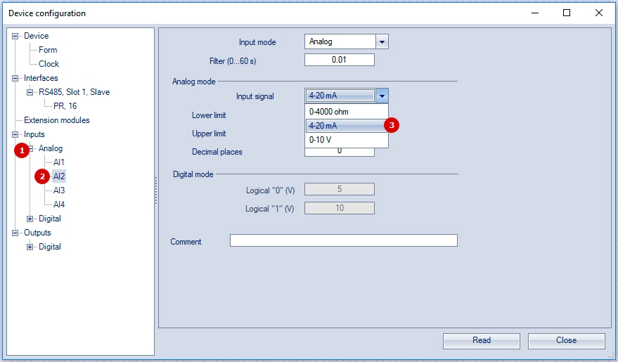
    How should I configure an analog input of the PR200?

    First, you should choose the required jumper position according to the figure below:

    You can find the jumpers under the front housing:

    All analog inputs are set to 4-20 mA in the delivery state.

    Second, you have to set the required input type in akYtec ALP:

    - From the Menu bar, select Device > Device settings or click the Device settings button 

    - In the tree view on the left, find the node Inputs, click Analog and select an analog input

    - On the right, select the required input type on the Input Signal drop-down list and set the required lower and upper limits

    - Click Close to save and exit.

    Rate the answer?
    The button 'Transfer application to device' is not available. What should I do?

    You need to update the firmware in the ‘Down.Mode’ mode.

    First, remove the front housing of the PR200 and set a jumper on the XP3 connector:

    The ‘Down.Mode’ mode has been activated. Open akYtec ALP and select Device > Firmaware update from the Menu bar:

    Select your device from the list and press the Select button.

    Rate the answer?
    How many PRM modules does the PR200 support?

    Maximum two modules can be connected in series to PR200.

    With these modules, you can extend the PR200 by up to 16 additional digital inputs and up to 16 digital outputs. Alternatively, if your system requires more I/O-points, you can use Modbus RTU/ASCII and connect up to 32 expansion modules over the RS485 interface. We recommend using our I/O-Modules of the Mx110 series for this purpose.

    Rate the answer?