Welcome to akYtec!
 
Call us now: +49 (0) 511 / 16 59 672-0

MSD200 Data logger

SKU: MSD200
The MSD200 data logger is designed for DIN rail mounting and has two RS485 interfaces. The device supports Modbus RTU and ASCII protocols.

EtherCATEtherCAT16DOrelaylookpoweredEtherCATEtherCATEtherCATEtherCATEtherCAT
- +
Product Description
    Details

    The MSD200 data logger is designed for DIN rail mounting and has two RS485 interfaces. The device supports Modbus RTU and ASCII protocols. 64 channels for data querying and archiving are available. The logger is equipped with four (0)4-20 mA analog inputs. The data are stored on an SD card. The integrated USB port enables data reading and device configuration. Use of the included programming tool makes the configuration and data handling easy and comfortable.

    Functions and features:

    • Archiving up to 64 data measuring points
    • SD cards up to 32 GB
    • 4 analog inputs
    • Automatic archive compilation for several days is possible
    • Express data analysis (extreme values identification)
    • Configurable archive memory
    • Data reading and device configuration via the USB interface

    Areas of application:

    The MSD200 can be used for data archiving in various processes in the food, chemical, gas and packaging industry as well as in the construction materials and wood processing industries. It can be also applied in many other areas of industrial and building automation.

    General
    Power supply 24 (20...33) V DC
    Power consumption, max. 5 W
    Number of channels, max. 64
    Logging cycle 1…65535 s
    Dataset size (per 1 channel) 20 byte
    Storage media MMC, SD, SDHC, microSD
    Storage capacity ≤32 GB
    Storage medium file system FAT32
    Analog inputs
    Quantity 4
    Input signals 0-5 mA, 0(4)-20 mA
    Sampling time for analog inputs 100 ms
    Accuracy ±1.0%
    Input resistance 133 ohm
    Galvanic isolation none
    Resolution 12 bit
    Communication
    Interfaces 2 x RS485 (RS1, RS2)
    USB-Device 2.0
    Protocol Modbus RTU / ASCII, akYtec
    RS485
    RS1 operation mode Slave (PC interface)
    RS2 operation mode Master/Slave (Device interface)
    RS1 protocol Modbus RTU
    RS2 protocol Modbus RTU / ASCII, akYtec
    Baud rate 1.2...115.2 kBit/s
    Galvanic isolation individual
    Environment
    Ambient temperature -10...+55 °C
    Humidity up to 80%, non-condensing
    IP Code IP20
    Enclosure
    Dimensions 22.5 x 102 x 120 mm
    Weight approx. 150 g
    Material plastic

    Data logging with MSD200 and evaluation with spreadsheet

    Data logging is a very common automation task which can be easily solved by means of products from akYtec. A quick and cost-effective solution based on Data Logger MSD200 we have implemented in the sample project below:

    Project description (part 1)

    Project description (part 2)

    Data logger

    We hope this project will be very helpful and save your time significantly.

Additional Information
FAQ

    FAQ

    When I lever the ARCH DIP switch in the ON position, the SD LED starts blinking green, i.e. the logging has begun. The blinking stops a few seconds later, and the LED remains green. Why does the MSD200 stop recording to the SD card, and how can I solve this matter?

    When the SD LED stops blinking and turns to constant green, the data start being temporarily stored in a 16 kB buffer. One minute later or when the buffer is full, the SD LED turns back to blinking, indicating that the data have started transferring to the memory card.

    Please remember: Do not remove the memory card when recording is not completed (the SD LED is blinking), in order to avoid violation of the file structure on the card.

    Rate the answer?
    What software do I need to program the MSD200? Do I need a specialized cable? Is this cable and an SD Card included on the delivery?

    To program the MSD200, you need the ‘MSD200 Configurator’ from akYtec. It is free of charge. You can find it either or on our website or on the USB Stick that is included in the delivery.

    For the connection of the MSD200 to a PC, a USB Cable of type A/B is required (not included).

    Yes, an SD Card (16 MB) is included in the box.

    Rate the answer?
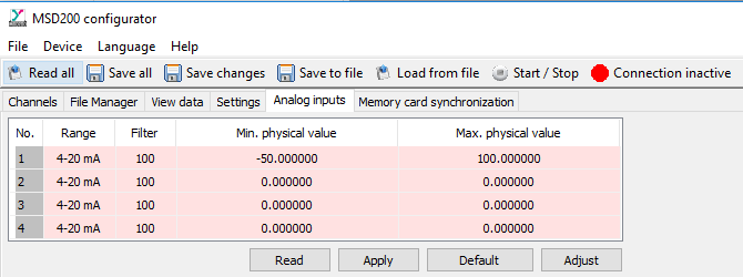
    Can I scale an analog input signal with the ‘MSD200 Configurator’?

    Yes, you should do that according to the measuring range of the sensor.

    For example, to log temperature using a DTS125L PT100 and an NPT1 that is connected to a 4-20 mA input of the MSD200, take the following configuration:

    Rate the answer?
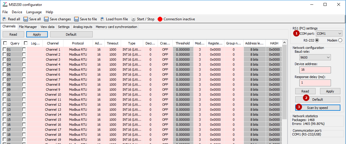
    Can I monitor Modbus registers and analog inputs in real time?

    Yes, you can monitor them in real time on the tab ‘View Data’ in the ‘MSD200 Configurator’ if the MDS200 operates as Master.

    If the MSD200 operates as Salve, you cannot view Modbus registers in real time. In this case, the Modbus registers contain data that are received by the latest command of the Master, which are not always real-time data. They are only real-time if the Master sends commands at a high enough rate. The analog inputs aren’t logged at all in this mode.

    Rate the answer?
    If there is a power loss on the MSD200, does the system restart with the set configuration in memory?
    Yes, the data logger will restart with the set configuration because this information is stored in the internal non-volatile memory of the device.
    Rate the answer?
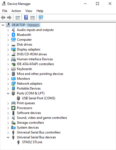
    I have installed the software and driver for the device. When I tried to connect to it, it keeps coming back with errors and cannot connect. What should I check?

    We recommend that you reset the data logger to its factory settings. Please, proceed as follows:

    - Close MSD200 Configurator

    - Disconnect the MSD200 from power and the PC

    - Set the DIP switch ‘FACT’-switch on the front panel of the data logger to ON position

    - Connect the MSD200 to power and the PC and wait for the device driver to be successfully installed

    - Open Windows Device Manager (‘Windows key + X’ and select ‘Device Manager’ from the menu). In the tree view, double click on the node ‘Ports (COM & LPT)’, look up ‘USB Serial Port (COMX)’. The X is the port number that the PC has assigned to the MSD200. Keep it in your mind for a few secs – you need it for the next step.

    - Open MSD200 Configurator, find ‘RS1 (PC) settings’ to the right of the window and select the COM port with the X from the previous step.

    - Click on the button ‘Default’ and then ‘Scan by speed’.

    If the connection cannot be established, please contact our technical support.

    Rate the answer?
    Do you have a short start guide that describes the startup of the MSD200 step by step using an example?

    Our video ‘MSD200 first start video tutorial’ must be very helpful for you.

    In addition, we also have a sample project with the MSD200 as the main device. The project is devoted to Data logging & Data Evaluation.

    Rate the answer?
    How can I get the log file from the MSD200?

    You can find this file (.CSV) file on the SD card inserted into the MSD200. from There are two ways to reach this file:

    - You connect the MSD200 to the PC and use MSD200 Configurator:

    - You remove the SD card from the MSD200 and connect it to the PC through a card reader

    Rate the answer?
    Is it possible to connect a 4-20 mA signal in series with the MSD200 and a control system to log the signal information?

    Yes, it is possible to do it, however, you should take into consideration the input resistance of the MSD200’s analog input (133 ohm).

    Rate the answer?
    Can I use the MSD200 to open/close a valve depending on the 4-20 mA signal to be logged?

    No, you cannot do this because the MSD200 has no outputs.

    In order to create a control system and log process data, we recommend using our Programmable Relay PR200 together with the MSD200. Contact us or visit our website to get more information.

    Rate the answer?
    How many Modbus Registers can be logged with the MSD200?

    The MSD200 Data Logger can log up to 64 Modbus Registers, one per channel.

    Rate the answer?
    What register addressing does the MSD200 use, decimal or hexadecimal?

    The MSD200 uses hexadecimal register addressing.

    Rate the answer?
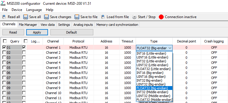
    I have connected a Slave Device to the MSD200. I am having problems reading INT and REAL variables. I check a value on the View Data tab, but the value doesn’t make sense. What should I check?

    To read and log variables, it is important to know the endianness of the register, that means to know the sequential order in which bytes are arranged. The words transmitted via Modbus can be represented as big-endian or little-endian and they will be sent/stored accordingly.

    To read and show REAL variables, it is important to know the endianness of the registers and bytes, i.e. register and byte ordering. It can be either big-endian or little-endian format.

    Register Endianness

    If you use the big-endian format, the register or the byte that contains the most significant bit is sent first, followed in a decreasing significance order. The little-endian format has a reversed order.

    You can select the endianness here:

    Rate the answer?
    How should I configure an analog input of the MSD200? Is it necessary to connect a shunt resistor to the input?

    To connect a signal to the MSD200 no shunt resistor is needed.

    To configure the required analog input, set the physical limits of the signal on the Analog Inputs tab.

    Rate the answer?