Welcome to akYtec!
 
Call us now: +49 (0) 511 / 16 59 672-0

MV210 Analog Input Modules (AI, Modbus TCP, Ethernet)

SKU: MV210 (AI)
The MV210 AI Series from akYtec represents a collection of input modules, working through Modbus TCP via Ethernet, expertly designed for precision and versatility in industrial automation systems. This series is tailored to handle a wide spectrum of analog signals, rendering it an essential component for data acquisition and process control across varied industrial applications.


8 analog inputshandUniversal inputsEthernet interfacebypassModbus TCPUSB interfacebuilt-in real-time clockLoggingsoftware at no chargeAmbient temperatureDIN rail mountingWall mounting


* Required Fields

- +
Product Description
    Details

    The MV210 AI Series from akYtec represents a collection of input modules, working through Modbus TCP via Ethernet, expertly designed for precision and versatility in industrial automation systems. This series is tailored to handle a wide spectrum of analog signals, rendering it an essential component for data acquisition and process control across varied industrial applications.

    Key Features of the MV210 AI Series:

    • Diverse Power Supply Range: The series operates within a 24 (10...48) V DC power supply range, with specific models having varied power consumption, ensuring adaptability and energy efficiency.
    • Comprehensive Safety Features: Each module is built with polarity protection and conforms to appliance class II standards, signifying a high level of safety and resilience in demanding industrial environments.
    • Advanced Data Communication: The series is equipped with Double Ethernet 10/100 Mbps interfaces for robust data transfer. The inclusion of USB 2.0 (micro-USB) and Ethernet 10/100 Mbps configuration interfaces facilitates flexible connectivity and system integration.
    • Broad Protocol Support: Supporting multiple protocols like Modbus TCP, MQTT, SNMP, and NTP, the series offers seamless integration with a variety of network architectures, enhancing its compatibility and utility.
    • Versatile Input Options: Modules in this series feature a range of analog inputs capable of interfacing with various signal types, including RTD, TC, and standard voltage/current signals. This versatility makes them ideal for a wide array of sensor types and industrial measurements.
    • Precision and Accuracy: The series boasts high ADC resolution, ensuring precise data acquisition. Each module is designed to offer low basic error rates across different input types, guaranteeing accuracy in critical measurements.
    • Integrated Data Logging and Clock Functions: Equipped with flash memory for data logging and real-time clocks, the series is well-suited for time-sensitive applications, offering comprehensive data tracking and time-stamping capabilities.
    • Environmental Durability: Designed to withstand challenging conditions, the modules operate effectively in a wide ambient temperature range and offer high humidity resistance, ensuring reliable performance in diverse settings.
    • Compact and Sturdy Design: The series combines a compact form factor with a durable enclosure, maintaining a balance between space efficiency and protection. The IP20 rating and robust material construction ensure longevity and resilience.
    • Scalability for Future Expansions: As the series evolves, new module additions are designed to seamlessly integrate with existing setups, maintaining the series' commitment to versatility and expandability.

    Feature

    MV210-101

    Power Supply

    24 (10...48) V DC

    Power Consumption, Max.

    4 W at 24 V DC

    Polarity Protection

    Yes

    Appliance Class

    II

    Data Transfer Interface

    Double Ethernet 10/100 Mbps

    Configuration Interfaces

    USB 2.0 (micro-USB), Ethernet 10/100 Mbps

    Protocols

    Modbus TCP, MQTT, SNMP, NTP

    Analog Inputs

    • Quantity: 8
    • Type: RTD, TC, 0-2(5) kohm, 0(4)-20 mA, -1...1 V (complete list in documentation)

    ADC Resolution

    16 bit

    Sampling Time per Input, Max.

    • RTD: 0.9 s
    • TC: 0.6 s
    • Linear signals: 0.6 s

    Basic Error

    • RTD: 0.25 % FS
    • TC: 0.5 % FS
    • Linear signals: 0.25 % FS

    Flash Memory (Log File Storage)

    • File size, max.: 2 kB
    • Number of files, max.: 1000
    • Logging interval, min.: 10 s

    Real-time Clock Accuracy

    • ±3 s/day at 25°C
    • ±10 s/day at 40°C

    Backup Battery

    CR2032

    Ambient Temperature

    -40...+55 °C

    Storage Temperature

    -40...+55 °C

    Humidity

    Up to 95%, non-condensing

    IP Code

    IP20

    Enclosure Dimensions

    42 x 124 x 83 mm

    Weight

    Approx. 260 g

    Material

    Plastic

Additional Information
FAQ

    FAQ

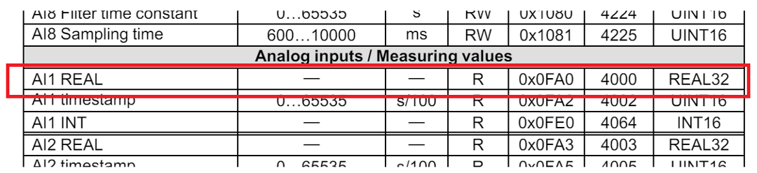
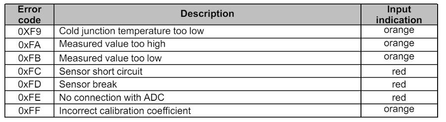
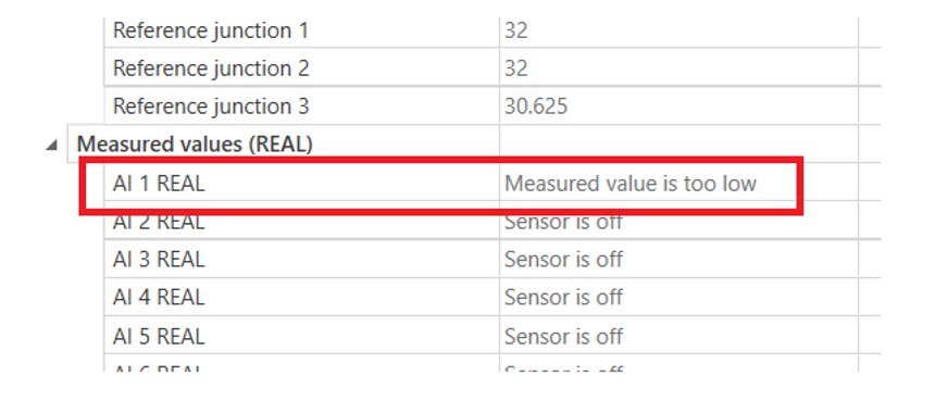
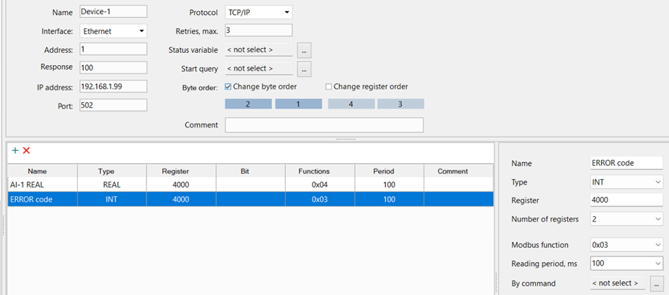
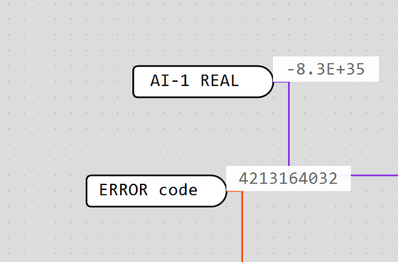
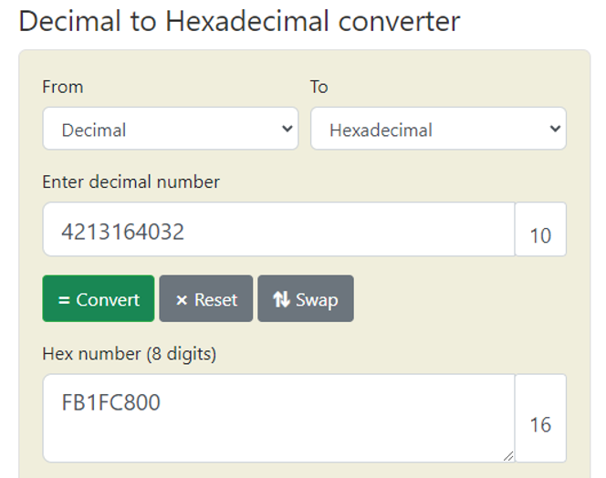
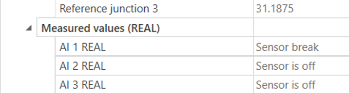
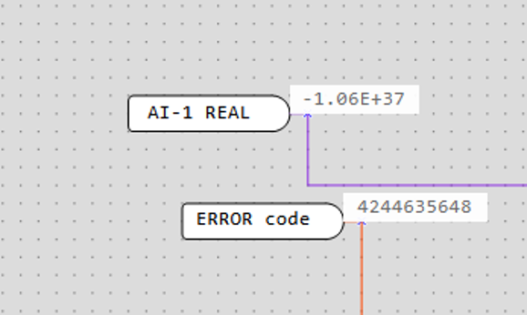
    How is the error message read from the MV210-101 device?

    1. User Guide

    As it says in User Guide (UG) on page 16 of device :

    “In case of an input error, the error code is written in the most significant byte of the corresponding AIn REAL register instead of the measured value.”

    So for example, if we are talking abour AI 1 then, address is :

    UG page 37

    Picture is taken from UG on page 37.

    List of some of the expected error codes:

    List of some of the expected error codes

    2. Example

    In akYtec Tool Pro we have simulated error on first AI:

    List of some of the expected error codes

    Now we need to read it with akYtec ALP….

    Here is a example of comunication configuration between PR103 and MV210-101:

    List of some of the expected error codes

    From the picture above you can see couple of things:

    1. Both variables have same register address, BUT the difference is in “Read function” ( 0x04 and 0x03) and in data type
    2. AI-1 REAL is used for reading regular signal data and ERROR code is used for reading code of an error

    Here is a view in ALP (online debuging mode), in situation when an error is present:

    List of some of the expected error codes

    Now, what you need to do is to take this integer value (data from ERROR code) to any decimal to hexadecimal converter, like this:

    List of some of the expected error codes

    ONLY IMPORTANT data is (from left to right) first 2, so in this case “FB”. Then you need to take this code to table with code description and see that this coresponds to “Measured value too low”.

    Note:

    Reason why we have code with 8 symbols in this example is because wee have taken whole number from variable instead of only highest byte!

    Don’t worry here is an example with “clean error code“

    3. Clean error code example

    List of some of the expected error codes
    List of some of the expected error codes
    List of some of the expected error codes

    By looking in table of error code:

    List of some of the expected error codes

    You can see that this method works.

    Rate the answer?
    Are Mx210 modules compatible with third-party PLCs?
    MX210 modules are compatible with any third-party PLC device if it supports Modbus TCP, MQTT,SNMP or SNTP communication protocols.
    Rate the answer?
    What software is required to configure the module?
    Modules can be configured on a PC with a free software ToolPro from akYtec. Modules need to be connected to a PC with a micro USB or Ethernet cable. An external power supply unit is required in case an ethernet cable is used.
    Rate the answer?
    I have forgotten the module network settings. How can I find them?
    It is necessary to restore factory settings by pressing and holding the service button located under the front cover of the module for more than 12 seconds, all while the module is powered on. Now, the device will operate with default parameters.
    Rate the answer?
    Is there a feature for group configuration of multiple modules?
    Yes, MX210 extension modules have this ability.
    Rate the answer?
    Is there a possibility to disconnect the terminal block?
    Yes, terminal block for I/O connections is removable and enables quick and easy replacement of the device.
    Rate the answer?
    How many devices can the module connect to?
    Any MX210 extension module can simultaneously communicate with up to 4 TCP clients, which facilitates cabling and configuring of the control system.
    Rate the answer?
    How to perform connection with modules?
    Modules can be implemented into a star or chain/daisy-chain topology, the latter providing data transfer directly from port 1 to port 2 if the module fails due to device error or power loss, thanks to two bypass-capable Ethernet ports. The maximum length of communication lines is 100 m.
    Rate the answer?
    Are circuits galvanically isolated?
    Every device from Mx210 product line has galvanic isolation, which is performed differently for each model and in groups, such as power supply, inputs/outputs, interfaces and housing.
    Rate the answer?
    Can the integrated voltage source of a PR200-230.X.X be used for feeding an input module MV210?
    No, this voltage source cannot be used for feeding an MV210 module because it doesn’t provide enough current (max. 100 mA).
    Rate the answer?
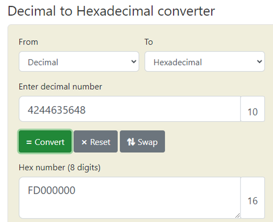
    In which numeral system should the register address be written, decimal or hexadecimal?
    The register address has to be written in decimal.
    Rate the answer?
    How does the Modbus register work and why is it in hexadecimal (3x0000 to 3xFFFF)?
    Modbus registers are typically 16-bit values, used to store and exchange various types of data, such as sensor readings, control parameters, status information, etc. These registers are represented in a hexadecimal format and organized in a range from 0x0000 to 0xFFFF, which covers 65,536 possible values. The 16-bit format is common in industrial control systems because it provides a good balance between precision and data size. Hexadecimal representation of binary data is more compact, efficient and offers better readability for 16-bit values than binary or decimal, as each hexadecimal digit represents four binary bits. Hexadecimal values also align neatly with bytes. In a Modbus register, each byte is represented by two hexadecimal digits, making it easier to work with when dealing with byte-oriented communication protocols. Hexadecimal representation is consistent with the way data is displayed and configured in industrial control systems and related software. The "3x" in "3x0000 - 3xFFFF" refers to the Modbus function codes. In Modbus, function codes 3 and 4 are used for reading and writing registers. The "x" in "3x" signifies that these registers are in the "holding registers" category. Holding registers are used to store data that can be read and written by external devices.
    Rate the answer?
    Can I use an analogue input as a discrete input?
    Yes, every analogue input can be configured and used as a discrete one.
    Rate the answer?
    How big is the ADC resolution?
    ADC resolution is 16 bit.
    Rate the answer?
    What steps do I have to take to calibrate the MV210-devices when i have uncertainties in the measurement?
    If the accuracy of the input or output of the module is no longer in accordance with the specification, it can be calibrated. Each analog input and output has its own calibration coefficients for each sensor type. – The calibration is performed using a reference signal source connected to the device input or output. – The calibration coefficients are calculated based on the ratio between the current input signal and the reference signal and stored in the non-volatile device memory. – If the calculated coefficients go beyond the permissible limits, a message about the error cause will be displayed.
    Rate the answer?