Product Description
- Configurable byte/register order for all operating modes.
- Displaying values like INT, DINT, WORD, DWORD, REAL, STRING, Portrait (bit mask of indicator segments), Time (value in the “xx:yy” format).
- Customizable number of leading zeros and decimal places
- Supports blinking and creeping modes.
- Possibility of linear scaling of the obtained value.
- Control of color, blinking and other parameters via Modbus registers.
- The presence of a built-in logic mode for changing the color and blinking mode in case of values outside the specified range.
- LED brightness control.
- Supports Modbus RTU/ASCII protocols in Master/Slave/Spy modes.
- Master - the indicator acts as a master device, polling another device and displaying the value of one of its parameters. This allows displaying data from a device that can only operate in slave mode such as TRM. The indicator's color changes and blinking are controlled by the indicator's built-in logic, as set by the user.
- Slave - the indicator displays a value received from the master device (e.g. PLC or PR). The indicator's color changes and blinking can occur either by command from the master device (according to its program), or by the SMI2-М's built-in logic. Multiple indicators can be connected to one RS-485 bus.
- Spy - mode allows the indicator to connect to the bus, where a master device is already present, and "listen in" on the traffic, waiting for requests or responses with specified parameters (device address, function code, register address). This enables the device to be used in existing systems where reconfiguration of the equipment is not possible. Another use case for this mode is synchronous data updating on multiple indicators using a broadcast from the master device to address 0. Each indicator is assigned an individual register number in the listened request, allowing each device to extract their own data from the broadcasted request.
Details
Functionality of SMI2-M:
|
Parameter |
Meaning |
|
Frame |
|
|
Dimensions |
48×26×65,4 mm |
|
Ambient temperature |
-40…70 °C |
|
Protection class |
III |
|
IP Code |
front IP65, rear IP20 |
|
Display |
|
|
Display type |
4-digit, 7-segment display |
|
Character height |
14 mm |
|
Display color |
Red\Green\Yellow |
|
Interface |
|
|
Interface |
RS-485 (2-wire bus) |
|
Protocols |
ModBus RTU / ASCII, akYtec |
|
Baud rate |
2.4...115.2 kBit/s |
|
Galvanic isolation |
Yes |
|
Configuration Interface |
MicroUSB |
|
Power supply |
|
|
Power supply |
24 (18...36) V DC |
|
Power consumption, max. |
1,5 W |

Documents And Software
- ePLAN
- STEP Model
 |
|
 |
|
|
|
| akYtec Tool Pro_v1.28.128.0 |
| SMI2-M |
|
ePLAN_SMI2-M (*.zip 11.4 mb)
|
|
|
STEP_SMI2-M (*.zip 2.95 mb)
|
|
Additional Information
FAQ
- What software do I need to configure the SMI2? Do I need a specialized cable?
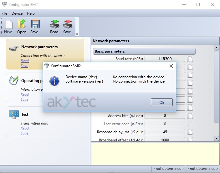
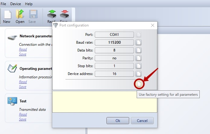
- I have successfully connected the SMI2 to my PC several times, but this time, an error message appeared. What should I check?
- Can I use the SMI2 with an Arduino board or a PLC from any company?